Orange Rockerverb 50 MK1 no channel switching

BesaMoogie

Well-known member
Hi, I need some help here.
My RV50 MK1 does not switch channels, it stays in the dirty channel all the time. Not only with the footswitch does not work, but also the switch on the front panel. So I think the problem is not related to the FS or the jack.
The footswitching for the reverb does also not work.

In the orange forum I red, that if the front panel switch does not work either, the problem is more likely related to relays or a chip etc.
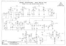
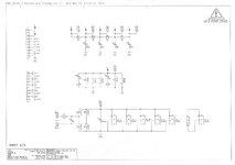
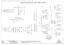
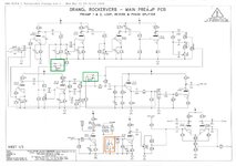
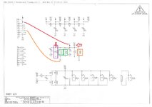
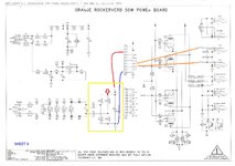
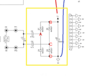
What is the best way to troubleshoot this? I attached some schematics of the RV50.

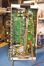
On a side note, the amp was not played for like 2-3 years. When I turned it on, I used a variac and brought up the voltage slowly up to prevent too much stress on the filter caps.

Thanks!
 

Attachments

  • RV50C_sheet1.jpeg
    RV50C_sheet1.jpeg
    167.1 KB · Views: 53
  • RV50C_sheet2.jpeg
    RV50C_sheet2.jpeg
    106.7 KB · Views: 48
  • RV50C_sheet3.jpeg
    RV50C_sheet3.jpeg
    174.3 KB · Views: 52
Take a regular mono guitar cable. Insert it into channel switch jack. Measure the voltage at the other end (ring- tip+). Now do the same on the reverb switch jack. Come back with voltages.
 
Take a regular mono guitar cable. Insert it into channel switch jack. Measure the voltage at the other end (ring- tip+). Now do the same on the reverb switch jack. Come back with voltages.
On both jacks (FS and Reverb) the voltage constantly "jumped" around between 28-29mV DC.
The front panel switch position did not affect the measuring.
 
To begin with, if you don't have experience with tube amplifiers and you decide to open it yourself, be very careful. Voltages are potentially lethal and they are present all over the PCB (i.e. in a red rectangle and ribbon cable connectors).

I am not familiar with Rockerverbs and don't know, which version you have. So the PCB may be different from what I found. But it should be at least similar.

From the schematic and your measurement I believe, there could be 2 reasons of the behavior.
- all 3 switching relays are burned or otherwise defective
- supply voltage for mentioned relays is not present

Channels are switched by relays RL1 and RL3 (green rectangles on schematics and photo). Reverb is switched by RL2 (orange rectangles). For the correct switching, supply voltage V+ must be present. Should be about 6V or so and should be measurable on switching jacks, that's why yesterday I recommended to measure it. This voltage is created by components in yellow rectangle.

1. with the amp turned off and disconnected from the mains!, measure with ohmmeter the path between anode of the D2 (non stripe pin, magenta rectangle) and the tip of the channel switching jack. Should be near 0 Ohm. This is just simple test to be sure the path is OK. If OK, continue.

2. turn the amp on and let it stay on standby! (this way you will get rid of most of high voltages on the PCB, but that doesn't mean, they are still not present in some parts of the amp).

3. measure the V+ on both PCBs. Good point for ground probe is on the ring of the switching jack, if you can not locate another one. Measuring points are marked by red arrows in schematics. Start on the D7 or D6 cathode (yellow rectangle, stripe marked pin near the English flag). If the voltage around 6V or so is present here, measure it on D2 cathode (magenta rectangle). If the voltage is present on both points, the problem is probably in relays. If it is not, there is a problem in a "yellow rectangle circuit".

edit: credits for PCB pics
https://irationaudio.com/2016/06/16/orange-rockerverb-50/
 

Attachments

  • RV50C_sheet1_.jpg
    RV50C_sheet1_.jpg
    271.3 KB · Views: 49
  • RV50C_sheet2_.jpg
    RV50C_sheet2_.jpg
    194 KB · Views: 42
  • RV50C_sheet3_.jpg
    RV50C_sheet3_.jpg
    298.4 KB · Views: 79
  • orange-rockerverb_.jpg
    orange-rockerverb_.jpg
    3 MB · Views: 56
Last edited:
To begin with, if you don't have experience with tube amplifiers and you decide to open it yourself, be very careful. Voltages are potentially lethal and they are present all over the PCB (i.e. in a red rectangle and ribbon cable connectors).

I am not familiar with Rockerverbs and don't know, which version you have. So the PCB may be different from what I found. But it should be at least similar.

From the schematic and your measurement I believe, there could be 2 reasons of the behavior.
- all 3 switching relays are burned or otherwise defective
- supply voltage for mentioned relays is not present

Channels are switched by relays RL1 and RL3 (green rectangles on schematics and photo). Reverb is switched by RL2 (orange rectangles). For the correct switching, supply voltage V+ must be present. Should be about 6V or so and should be measurable on switching jacks, that's why yesterday I recommended to measure it. This voltage is created by components in yellow rectangle.

1. with the amp turned off and disconnected from the mains!, measure with ohmmeter the path between anode of the D2 (non stripe pin, magenta rectangle) and the tip of the channel switching jack. Should be near 0 Ohm. This is just simple test to be sure the path is OK. If OK, continue.

2. turn the amp on and let it stay on standby! (this way you will get rid of most of high voltages on the PCB, but that doesn't mean, they are still not present in some parts of the amp).

3. measure the V+ on both PCBs. Good point for ground probe is on the ring of the switching jack, if you can not locate another one. Measuring points are marked by red arrows in schematics. Start on the D7 or D6 cathode (yellow rectangle, stripe marked pin near the English flag). If the voltage around 6V or so is present here, measure it on D2 cathode (magenta rectangle). If the voltage is present on both points, the problem is probably in relays. If it is not, there is a problem in a "yellow rectangle circuit".

edit: credits for PCB pics
https://irationaudio.com/2016/06/16/orange-rockerverb-50/
Hi, thanks for the instructions! I will find some time tomorrow to do the measuring.
I`m fine with working on amps, I was able to put together a plexi clone kit without killing myself ;)
 
To begin with, if you don't have experience with tube amplifiers and you decide to open it yourself, be very careful. Voltages are potentially lethal and they are present all over the PCB (i.e. in a red rectangle and ribbon cable connectors).

I am not familiar with Rockerverbs and don't know, which version you have. So the PCB may be different from what I found. But it should be at least similar.

From the schematic and your measurement I believe, there could be 2 reasons of the behavior.
- all 3 switching relays are burned or otherwise defective
- supply voltage for mentioned relays is not present

Channels are switched by relays RL1 and RL3 (green rectangles on schematics and photo). Reverb is switched by RL2 (orange rectangles). For the correct switching, supply voltage V+ must be present. Should be about 6V or so and should be measurable on switching jacks, that's why yesterday I recommended to measure it. This voltage is created by components in yellow rectangle.

1. with the amp turned off and disconnected from the mains!, measure with ohmmeter the path between anode of the D2 (non stripe pin, magenta rectangle) and the tip of the channel switching jack. Should be near 0 Ohm. This is just simple test to be sure the path is OK. If OK, continue.

2. turn the amp on and let it stay on standby! (this way you will get rid of most of high voltages on the PCB, but that doesn't mean, they are still not present in some parts of the amp).

3. measure the V+ on both PCBs. Good point for ground probe is on the ring of the switching jack, if you can not locate another one. Measuring points are marked by red arrows in schematics. Start on the D7 or D6 cathode (yellow rectangle, stripe marked pin near the English flag). If the voltage around 6V or so is present here, measure it on D2 cathode (magenta rectangle). If the voltage is present on both points, the problem is probably in relays. If it is not, there is a problem in a "yellow rectangle circuit".

edit: credits for PCB pics
https://irationaudio.com/2016/06/16/orange-rockerverb-50/
Ok, I made the measuring.
The path between anode of D2 and the jack was ok.
On the cathodes of D2, D6 and D7 (and TP4) I measured the same 28 to 29 mV as on the switching jack before.

So is the problem in the components of the yellow rectangle circuit?
I had a look at the components. No bulging on the caps and no burnt marks on the diodes.
 
Last edited:
Yes, you should check voltages (AC as well) starting on TP1 and TP2, continue to the "yellow circuit". What is strange, it seems on the pic, that C9 is not mounted (also no value is specified in the schematic). Is it the same on your board? Is there a jumper instead?
 
Yes, you should check voltages (AC as well) starting on TP1 and TP2, continue to the "yellow circuit". What is strange, it seems on the pic, that C9 is not mounted (also no value is specified in the schematic). Is it the same on your board? Is there a jumper instead?
No, there is not cap present on C9 and there is no jumper installed.
I did some measuring, AC and DC. Here is a list of the results and the picture indicates the points I measured:

AC measuring:
TP1 3 Volt
TP2 3 Volt
A. 0.84 Volt
B. 0.065 Volt
C. 0.05 Volt
D. 0.06 Volt
Tip/Ring switching jack 0.06 Volt


DC measuring:
TP1 0 Volt
TP2 0 Volt
A. 0.03 Volt
B. 0.03 Volt
C. 0.007 Volt
D. 0 Volt
Tip/Ring switching jack 0.03 Volt
 

Attachments

  • RV50 Yellow Messpunkte.png
    RV50 Yellow Messpunkte.png
    364.7 KB · Views: 33
Could be faulty C6. However, I must admit, that I am confused. If there is no C9, there should be no voltage on C8 after rectifier and it is not there... This makes no sense to me. Without mains, measure the resistance between D and TP2, also C and TP2 please.
 
Could be faulty C6. However, I must admit, that I am confused. If there is no C9, there should be no voltage on C8 after rectifier and it is not there... This makes no sense to me. Without mains, measure the resistance between D and TP2, also C and TP2 please.
D to TP2 was 0 ohm Resistance

Witch C to TP2 it was more complicated. Depending on where I put the red probe of the multimeter, I got different readings.
C to TP2 with red probe on C was 9.72 kohm
C to TP2 with red probe on TP2 was 62.2 kohm
B to TP2 was 0 ohm Resistance as well


Then I remeasured everything with my second cheap china multimeter. Here I got:
D to TP2 was 0 ohm Resistance
B to TP2 was 0 ohm Resistance
No reading (infinite Resistance?) on C to TP2 independent of where I put the red probe.

So it looks like D7 and D9 both have no resistance?
 
OK, so old and so stupid. Unused C9 confused me. Then I was missing ground connection from the heaters supply (orange wires). That's why I asked you to measure resistance between D and TP2. But I missed that center tap of the heater winding is connected to the ground.

So, most probably there is defective one or more of C6, D7, D9. Less probably D6, D8, C8.

But. If they are defective, that can be caused by failure of some relay. So, make two more measurements, resistance between tips of footswitch jacks and B (or TP4), with inserted patch cable, or guitar cable into both jacks. You should measure non-zero resistance in a range of tens to hundreds of Ohms (depends on relays used). In case of some crazy value, swap probes. There is a relatively big cap in the circuit as well, so it could take some time for the value value settle down. The resistance on the reverb jack should be 2x higher than on the channel jack, where there are 2 coils in parallel.

If the resistance is as I described, you can even apply external voltage around 5V to TP4 (+) and a tip of the jack (-), to test relays. Of course with the amp completely turned off. However, power supply with a current limit function would be the best. Or you can use 9V stompbox adaptor with let say 100 Ohm resistor in series.
Not as stupid as me I guess :)

Ok, I inserted a patch cable in the jacks of the channel and reverb switch.
The measuring from the tip of the jack to B / TP4 gave a resistance of 47.6 ohm on both jacks, no matter which probe I used.
So the relays are faulty to?

Wouldn`t it make sense to use the "brute force" method and simply replace C6, C8, D6, D7, D8, D9 as well as the relays as I have to pull out the board anyway for the work?
 
Hmm, in such a case, it seems that at least one of the relays is faulty. Still the coil resistance is quite low, like 3V relays and I believe there are G5V1 5V version relays used.

Of course, brute force. I wanted to give you advantage of:
- just one board out
- no collateral damage in case of bad diagnostics

So you can still try to test relays with an external supply, or just go ahead and replace everything, those components are few Euros.
Yes, those are G5V-1 5VDC relays used. I do have a variac I could set up to 5V but I can`t control the current on this.
So when applying the voltage, what should happen with the relays? How would you connect the 5V to the system, with crocodile clips?
 
When applying voltage, relays should switch, you should even hear that, or feel with tip of the finger. Except of that, you should be able to measure between pins, i.e. connection between R5 and R12.

If you don't have current limiting power supply, you can use 9V stomp box PS and 56 - 100 ohm resitor. How to connect? Again, two patch cables to switching jacks. Clip minus to the tip of the reverb patch cable i.e. with crocodile, or simply wind it around the tip. Use any wire from plus and touch TP4 shortly with it. If that works, you can try channel switch patch cable tip in the same way.
 
Ok, I will look if I try this, but I`m not sure, how easy it will be to asses the functionality of the relays. When holding the cable with the 5 Volts to TP4 I kind of miss one free hand to do the rest of the work ;)
I ordered the parts and they should arrive next week.

I redid the resistance measuring of the tip from the switch to TP4 because I previously patched both switches together when doing this ( I misunderstood this). This time I did it "separately". It was 82 ohm for the channel jack and 112 ohm for the reverb.
 
If there is no short circuit during the first "touch" to TP4, you can simply hook up that wire to let say cathode of D6 or D7. Then you will have both hands free :)

That measurement of resistance is weird, reverb circuit resistance should be about twice of the channel. Could be variation in coil resistance, but could be one defective relay in channel switching as well. You will see.
 
Back
Top