You are using an out of date browser. It may not display this or other websites correctly.
You should upgrade or use an alternative browser.
You should upgrade or use an alternative browser.
Elevated Heaters From A PT With No CT, WTF ?
- Thread starter Arch Stanton
- Start date
SpiderWars
Well-known member
Post #12 but add the 220k like #15. You need the 220k to the new node AND the 100k to ground. And the 100k to ground is in parallel with the cap, just like #12. But then instead of connecting the 220k to point B, connect it to point A.
SpiderWars
Well-known member
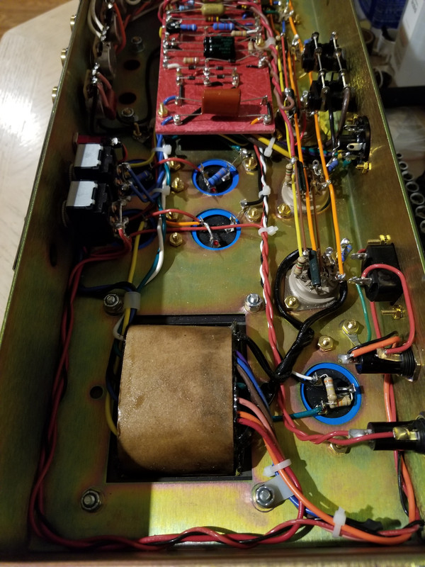
Here's a pic of my Superlead build. Look at the blue 100u+100u cap can on bottom right. One of the 100u (the top one) is for the PI and then there is a 330k to the other 100u with a 82k resistor in parallel to the ground lug. I did not use flameproof as @glpg80 suggests, I learned something in this thread and hope to fix that someday.
EDIT: Looks like I changed the 330k to 390k or maybe that pic is when I first built it. I remember settling on 58vdc when I ran it at 120vac power.
There is a black wire connected to the ground lug that is hard to see, it routes that ground to a better ground point.
EDIT: Looks like I changed the 330k to 390k or maybe that pic is when I first built it. I remember settling on 58vdc when I ran it at 120vac power.
There is a black wire connected to the ground lug that is hard to see, it routes that ground to a better ground point.
Last edited:
Arch Stanton
Dollar Store Satriani
Post #12 but add the 220k like #15. You need the 220k to the new node AND the 100k to ground. And the 100k to ground is in parallel with the cap, just like #12. But then instead of connecting the 220k to point B, connect it to point A.

SpiderWars
Well-known member
Bingo. Then measure and see what you get, you might have to adjust but that should be ballpark.
Arch Stanton
Dollar Store Satriani
Awesome ! Thanks my dudes !Bingo. Then measure and see what you get, you might have to adjust but that should be ballpark.
So I learn something here... why tap off A rather than B ?
And by "adjust" you mean the value of the 220KΩ resistor, right ? Target would be +/- 45V
Last edited:
T Wilcox
Active member
30-60V per Merlin works fine. You have some playAwesome ! Thanks my dudes !
So I learn something here... why tap off A rather than B ?
And by "adjust" you mean the value of the 220KΩ resistor, right ? Target would be +/- 45V
That circuit as is should put you right around 40V
Last edited:
Arch Stanton
Dollar Store Satriani
Excellent !30-50V per Merlin works fine. You have some play
That circuit as is should put you right around 40V
I'm going to lose about 32mA thru the two 100Ω resistors.. right ?
So it would be better to use the 200V tap instead of the 180V ?

T Wilcox
Active member
Not quite following.. the 32mA is from the 6.3V with 2A on tap so whichever Ht sec you choose shouldnt matter but I'd probably use the 200 since the snork drawing shows 250V.Excellent !
I'm going to lose about 32mA thru the two 100Ω resistors.. right ?
So it would be better to use the 200V tap instead of the 180V ?
At 150mA per 12AX7 and that 32mA you are still using less than 500mA
Arch Stanton
Dollar Store Satriani
Awesome !Not quite following.. the 32mA is from the 6.3V with 2A on tap so whichever Ht sec you choose shouldnt matter but I'd probably use the 200 since the snork drawing shows 250V.
At 150mA per 12AX7 and that 32mA you are still using less than 500mA
Thanks guys !
Arch Stanton
Dollar Store Satriani
Hey Todd, can you PM here yet ?Not quite following.. the 32mA is from the 6.3V with 2A on tap so whichever Ht sec you choose shouldnt matter but I'd probably use the 200 since the snork drawing shows 250V.
At 150mA per 12AX7 and that 32mA you are still using less than 500mA
What's that 330pF Wima cap across the mid pot ? I can tell if it's the mid pot, but I think it is.
Does not show up on the schematic.
T Wilcox
Active member
No , Im only at 36 messages here, 14 to go LOLHey Todd, can you PM here yet ?
What's that 330pF Wima cap across the mid pot ? I can tell if it's the mid pot, but I think it is.
Does not show up on the schematic.
Im at work replying from my phone so cant see the layout to answer your question
T Wilcox
Active member
It looks like the cap across the mid pot is .0047uF and is a low pass that is shunting some signal to ground.Hey Todd, can you PM here yet ?
What's that 330pF Wima cap across the mid pot ? I can tell if it's the mid pot, but I think it is.
Does not show up on the schematic.
Post #14 of this thread (hope its okay to link threads from other forums) https://www.marshallforum.com/threads/bright-cap-jcm800-4104.93525/
shows the schem for the 4010 JCM800 combo which has same cap across mid pot. The assumption is it was to compensate the tone difference between an open back combo and the jcm800 head.
This thread: http://www.groomednoodlers.com/forum/viewtopic.php?f=20&t=2636 confirms that the original Snorkler was a modded 4010 combo so this was all Marshall
Arch Stanton
Dollar Store Satriani
You're right, sorry.Include the fuses in your schematic. I’m dead nuts serious about this when doing tricks like floating AC on DC from the same source with something like vacuum tubes especially with todays quality.
I was so focused on working this out in my mind, I forgot to show the fusible links.
Arch Stanton
Dollar Store Satriani
Ok, that's what I was assuming was going on there with that cap.It looks like the cap across the mid pot is .0047uF and is a low pass that is shunting some signal to ground.
Post #14 of this thread (hope its okay to link threads from other forums) https://www.marshallforum.com/threads/bright-cap-jcm800-4104.93525/
shows the schem for the 4010 JCM800 combo which has same cap across mid pot. The assumption is it was to compensate the tone difference between an open back combo and the jcm800 head.
This thread: http://www.groomednoodlers.com/forum/viewtopic.php?f=20&t=2636 confirms that the original Snorkler was a modded 4010 combo so this was all Marshall
Thanks again !
glpg80
Well-known member
Ok, that's what I was assuming was going on there with that cap.
Thanks again !
Yeah he jogged my memory - that cap across the mid pot is indeed a compensation for open back versus closed back cabinets.
glpg80
Well-known member
You're right, sorry.
I was so focused on working this out in my mind, I forgot to show the fusible links.
Yes we get ahead of ourselves and the reason I mentioned it again after the bold text prior was that if you don’t put it in the schematic, you’ll likely also forget it later on during assembly. Not trying to be an ass, just trying to make sure you’re building something safe.
Arch Stanton
Dollar Store Satriani
I'm building in an old combo amp chassis. The mains wiring, mains fuse, pilot light are all already in place.Yes we get ahead of ourselves and the reason I mentioned it again after the bold text prior was that if you don’t put it in the schematic, you’ll likely also forget it later on during assembly. Not trying to be an ass, just trying to make sure you’re building something safe.
The existing mains fuse is 1A 125V.. should I use a lower rating there ?
On the secondary I'd need to add another fuse holder. I'm thinking a 500mA fast-acting for that one ?