1974 120W SL/A Restoration Project v2.0

SpiderWars":3gfowhqs said:
I have an old Kenwood...those old instruments are pretty cool and mine seems sturdy. But it's not like I do anything very useful with mine. Can you just pull the fuse and measure across the fuseblock instead of using the c-clamp?

Not a good idea just in case something is shorted on first turn on. I’d need to reduce the meter’s fuse to a 4A fast blow which I don’t think exists in the shatter proof fuses. Those things even when they are available are insanely expensive. It costs to be stupid lol
 
Most relay control functions wired with shielded wire. Only the effects loop is left, and I’m wiring it as we speak externally to be able to scope the signal levels to match it correctly.

I also modified the effects loop so that the line level or instrument level switch will become the toggle switch. I plan to wire it temporarily as mounted and will then shorten the wires slightly for proper mounting.

I also plan to mount the effects loop upside down so that send is on the left when facing the rear of the amp, and not on the right.

Once I have the effects loop mounted externally, I plan to build my own 4 tube bias probe off of an external meter. They’re so expensive and 4 tube models are made in China and with questionable hardware.

The reason for the bias probe is so that I can reinstall and bias the original tubes to get the correct plate voltage measurement to know what B+ dropping resistor is needed for the effects loop.

It’s getting there slowly. I’ll have more updates on the bias probe design next.
 

Attachments

  • BE3003BE-3CA3-4BFF-9DE9-0F0B1DF86ED4.jpeg
    BE3003BE-3CA3-4BFF-9DE9-0F0B1DF86ED4.jpeg
    393.8 KB · Views: 628
I finished the footswitch controls for the amplifier. The black wires are to add some stability to the small somewhat fragile signal wires, and aren’t connected or used for any purpose. The small signal wires are double shrink wrapped - once as twisted pairs after the initial splice and again near the plugs to provide more stability and to hold them to the black dummy wires. I used clear so that I could match the wires to labels later on and also keep an eye on wear/tear down the road.
 

Attachments

  • 8CC40231-B772-45FA-BB06-D5B7EEA2F5C7.jpeg
    8CC40231-B772-45FA-BB06-D5B7EEA2F5C7.jpeg
    84.3 KB · Views: 565
  • 00A765B3-5638-4574-B53E-197D89D20004.jpeg
    00A765B3-5638-4574-B53E-197D89D20004.jpeg
    70.6 KB · Views: 571
Spent today making progress on my quad socket octal bias probe. Couldn’t find anything I wanted on the market for reasonable prices and build quality, so I’m making my own.

The box and segments are wired and ready for calibration, next I need to complete each of the four octal current probes.
 

Attachments

  • 858D13CC-C807-42E2-8B4A-78A094AEECDA.jpeg
    858D13CC-C807-42E2-8B4A-78A094AEECDA.jpeg
    359.3 KB · Views: 507
Forgot to mention, I also got delivery of these
 

Attachments

  • ABF138D2-1AD3-4E4F-ADA3-635F055B0E4F.jpeg
    ABF138D2-1AD3-4E4F-ADA3-635F055B0E4F.jpeg
    323.7 KB · Views: 491
Well as a small update, my chinese 8 segment auto-ranging displays have failed me.

They came delivered with no datasheets which I thought was purplexing, but I continued designing my quad bias probe box anyway. They did auto range and measure their own respective 9V battery voltage correctly, so I did perform a function test of them individually upon arrival.

What I did not anticipate though, was that their range was stated to work from 0V to 100V. That to me meant they should measure 0.01 to 0.05 ranges just fine when in fact they displayed 0.0V the entire time. They couldn't register anything less than 100mV minimum.

I ordered a new box, new rotary switch, and supporting plug hardware to make a 4 way bias probe measurement tool that can utilize an external meter. I'll simply cut the probes off the current box (not worth the time to unsolder what is there) and re-use them as a pluggable probe into the box. In this manner, I will have the ability to measure anywhere from 2 tubes to 4 tubes at a time. The probes themselves will be modified with banana plugs so that any single probe can work with a multimeter.

It's a large setback on the bias measurement tool, but lesson learned. Keep it simple.

I need this bias probe so that I can bias the amplifier with the tubes installed, otherwise, my B+ voltage will be incorrect for the metro-loop install.

Anyway that's my update.
 
Dang, that sucks. Do they make them in a 0-1v range?

Also, just curious but do these measure plate current or cathode current? It just occurred to me that it would be really cool if you could somehow measure plate and screen current separately. It seems screen current creeps up as a tube ages so maybe could be an indicator that tubes are spent and time to consider changing them. If it's an amp one uses a lot they might notice it by listening but some amps get used, then not used for a while so you may not notice it as easily. I've also noticed that some tubes within a matched quad just don't age as well as the others and screen current varies a lot when old. This was evident in my Rocket clone which runs the EL84s pretty hard just at idle.
 
I measure cathode current mainly for safety and simplicity. I could have made a low tolerance voltage divider to measure plate voltage and plate current both, but it complicates the probes in an already space constricted design.
 
I finally had time to physically make my second attempt at a bias control box. It allows you to use an external multimeter of your choice for measuring as many or as little probes as you desire, just not all at once like my prior attempt. I simply switch between them to find the most-drifted tube and then set the bias (60% PD) from there.

I plan to get it wired up this weekend.
 

Attachments

  • C5411F7B-B1E6-4DB3-B626-E42F621F2E52.jpeg
    C5411F7B-B1E6-4DB3-B626-E42F621F2E52.jpeg
    249.6 KB · Views: 400
Felt motivated to modify the metroloop and install/route the shielded input/output signal lines. I have to install the external send level switch next.
 

Attachments

  • AB6EF1F6-B02B-4653-97D9-21467EB2822F.jpeg
    AB6EF1F6-B02B-4653-97D9-21467EB2822F.jpeg
    329.3 KB · Views: 297
  • B785BB4B-6EC5-4448-B338-D0AFADD066E6.jpeg
    B785BB4B-6EC5-4448-B338-D0AFADD066E6.jpeg
    305.2 KB · Views: 303
  • EC55050A-2065-4E5D-957B-7A3EDA8D9E13.jpeg
    EC55050A-2065-4E5D-957B-7A3EDA8D9E13.jpeg
    399.3 KB · Views: 295
Effects loop officially installed and modified for external send level control and shielded in/out wires. All that is left is to finish the relay connection and then start cleaning up the wiring with zip ties, calibrate the DC supply level to its highest setting, verify individual bias control voltage functionality, slowly form the filter capacitors on initial B+, install and bias the tubes with my tool that I built, measure plate voltage under load to install the proper loop dropping resistor, calibrate the effects loop level, measure footswitch voltages, and then verify relay board functionality is correct. After that button it up and it’s done.
 

Attachments

  • 43DA1F2B-796E-41C8-BA1D-19EA9397273A.jpeg
    43DA1F2B-796E-41C8-BA1D-19EA9397273A.jpeg
    413.6 KB · Views: 291
Some quick updates of the finished work
 

Attachments

  • 5B45F004-17AB-48D1-B08D-8409D4B094FF.jpeg
    5B45F004-17AB-48D1-B08D-8409D4B094FF.jpeg
    267 KB · Views: 263
  • 36DCC563-FFD0-47C5-8F27-7D90A6CC1B26.jpeg
    36DCC563-FFD0-47C5-8F27-7D90A6CC1B26.jpeg
    354.8 KB · Views: 249
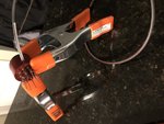
Just wanted to state the marshall is completed and wrapped up. The chassis was signed with an official completion date of 10/10/2020.

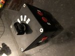
I've named it the blue-collar mod :rock:

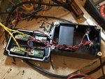
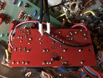
Two original potentiometers needed to be replaced - one due to mechanical failure from previous work, and another due to a dead spot or poor function at low value.

--

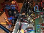
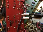
The amplifier biased up and the tubes drifted a bit needing correction, but it stabilized at 46mA at 460V loaded B+ which put it well within the safe range of 60% AM PDR using absolute max ratings of 42W/tube.

Tonal notes - it has much less gain than before the complete rework, but the resonance mod added a lot of low mids. It's much more clear sounding now overall - not as grainy and not as muddy as before likely due to the higher B+ and fresh set of tubes all around.

Noise wise it is the quietest marshall I have ever played - at full tilt through a small 1x8" speaker with the volume pot on 0 on the guitar, it was quiet as a mouse. Virtually no hiss.

I cannot wait to grab an SD-1 and stick it in front! It turned out great and it feels amazing to have accomplished this build.

Thank you all for your help - It's a one of a kind build that is my own and it is everything I could have wanted out of a vintage marshall tone and more.
 

Attachments

  • 5C09BFC4-E65E-4449-8A7F-AC86D9BBA38F.jpeg
    5C09BFC4-E65E-4449-8A7F-AC86D9BBA38F.jpeg
    140.7 KB · Views: 214
  • 1A5E76A3-F67A-4635-87C3-03BDE3EADE0B.jpeg
    1A5E76A3-F67A-4635-87C3-03BDE3EADE0B.jpeg
    150.4 KB · Views: 210
  • 321FBB79-66C1-449B-AF21-06AA95B73B71.jpeg
    321FBB79-66C1-449B-AF21-06AA95B73B71.jpeg
    138.8 KB · Views: 210
Last edited:
SpiderWars":2ai9oani said:
It must feel pretty rewarding to complete such an ambitious build. It looks top notch. Congrats!

Much thanks :rock:

It was fairly ambitious but this poor amplifier needed a new life brought back. In its previous condition, it really was in a downward spiral state - something was going to give.

It's an old amp that sounds fresh and isn't a basket case of noise and stability issues - a JMP that cuts like a knife and sounds huge. I'd put it up against any 2203x any day and also have more live-friendly features along the way. I couldn't really ask for more honestly. I designed it to do that Ozzy tone from no more tears. All I need is to grab an SD-1 to see if it comes alive as it did before the rebuild.

Overall - the main character hasn't been touched. It just doesn't sound tired and worn out - undefined. It sounds much better and was built to be reliable :rock:

I have a lot of hand-drawn schematics that have notes and modifications made along the way to accompany the needs of physical layout requirements. I need to now go through them and clean them up and make final versions of what is there so that they can be electronically scanned. I also need to make a voltage table for troubleshooting in the future.
 
SpiderWars":3ezov49p said:
It must feel pretty rewarding to complete such an ambitious build. It looks top notch. Congrats!
Yup! Nicely done :rock:
You put a lot of effort in to this, and I'm glad it turned out so well.

Congrats :thumbsup:
 
I finally got around to making a video of this thing.

NOTE: These are not my modifications tonally, just the amp restored to working order.

 
Last edited:
Back
Top