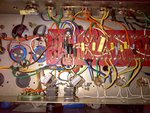
No need to argue on here fellas, I appreciate everyone's assistance thus far so I have no problem entertaining ideas. Am I over my head? Somewhat, but I spent today looking at the right schematic for the amp and the only thing I can see is that I have my red and black choke wires reversed in terms of where they connect on the schematic but I am not entirely sure that this would be a factor seeing as there are plenty of chokes I thought where this is not an issue. Second, my bias/trim pot wiring. I am thinking of looking at that more closely again as I might have made a mistake somewhere.
Voltage wise, all preamp and output tubes checked out within spec of what an 800 would have but slightly lower as the transformer doesn't seem to run as high. (397 plate voltage) I don't have a scope as this is not something I do full time. I usually just alter preamp sections of my amps for tinkering and learning. Maybe i was feeling ambitious with this one.
In reading his post there's enough to know he's in over his head and shouldn't be turning on the amp for measurements. The voltage selector switch wiring is part of the power transformer primary and should be nowhere near the high voltage secondary side or after rectification.
The 100 watt amp uses a center tapped winding for B+, the 50 watt does not so they can't be wired the same.
Why don't you tell me what you really think? lol

I am aware of where the voltages that kill are. I also incorrectly indicated that one of the wires was headed into the voltage selector switch when i should have indicated that it was run in that general direction and appears to be run to the fuse.(where it should be) When you were learning about amps, did you know everything about the circuit? I have no plans of becoming a Friedman or other. I just wanted an amp i could tinker with and try diff mods. That' why the PTP went in.
I also double checked my wiring to the power section from the transformer in the schematic and that is how I have it run. brown to standby and to rectifier, orange to ground and to diode on the board.