Couple questions about the 50 watt Ceriatone chupa B+

  • Thread starter Thread starter screamindemon
  • Start date Start date
screamindemon

screamindemon

Well-known member
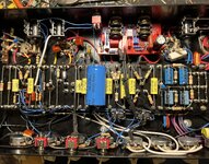
How are you guys implementing the 10k dropping resister after the phase inverter ? Was just wondering if someone had a easier way than pulling the board and adding underneath.

Also I have 220k grid leak resistors at the phase inverter, layout calls for 110k. Is this because of the dual bias and should I change them to 110k. When building I just copied the 2204 but maybe that was a mistake ? I added a pic for reference.
Thanks in advance.
 

Attachments

  • 59174AAF-D45C-4BA9-AD39-7B909857204B.jpeg
    59174AAF-D45C-4BA9-AD39-7B909857204B.jpeg
    3.6 MB · Views: 85
What amp is that @screamindemon ? I didn't think the Chupa had relays. And I didn't think it had that small cap across the NFB resistor either.

Regarding the grid bias resistors, I think 220k sounds and feels more punchy and firm. You can use either but you could try tacking another 220k on each one, check bias, and then listen. It shouldn't change the bias much but I ALWAYS recheck bias after messing with the bias circuit.
It’s a custom build I did based off a chupa kit. I had Nik make a lot of changes to the chassis to suit my needs. Relays are for gain boost, switching masters and switching the loop in and out. It’s a 4 gain stage with a plate driven tone stack.
 

Attachments

  • 6AF29DBA-AFE1-4247-9FB3-E4EE53787A44.jpeg
    6AF29DBA-AFE1-4247-9FB3-E4EE53787A44.jpeg
    2.4 MB · Views: 73
  • A74D6442-61F5-41C6-99B2-BA7847424408.jpeg
    A74D6442-61F5-41C6-99B2-BA7847424408.jpeg
    2.4 MB · Views: 71
I have a vid on the B+ issue, you can do it without pulling the board around the 14 min mark.

I watched your vid, nice info in there but that is a 100 watt with the filter cap mounted to the top of the chassis. Mine is a 50 watt with filter cap mounted to the board. I believe I will have to pull the board to make the change.
 
What amp is that @screamindemon ? I didn't think the Chupa had relays. And I didn't think it had that small cap across the NFB resistor either.

Regarding the grid bias resistors, I think 220k sounds and feels more punchy and firm. You can use either but you could try tacking another 220k on each one, check bias, and then listen. It shouldn't change the bias much but I ALWAYS recheck bias after messing with the bias circuit.
Also thanks for the info on the bias resistors ! ?
 
Also thanks for the info on the bias resistors ! ?
Could you just unsolder and lift the cap lead and then somehow install the resistor between the board turret and the flying lead?
And then your other 10k resistor would also connect to this point, giving it more rigidity.
 
I watched your vid, nice info in there but that is a 100 watt with the filter cap mounted to the top of the chassis. Mine is a 50 watt with filter cap mounted to the board. I believe I will have to pull the board to make the change.
Oh sorry, I didn’t realise.

The PI node supply is running under the board right? If you pull off that dual can cap, and unscrew the board itself you should be able to just get under it to remove that link. If you heat the turret itself you will be able to pull out the wire that is soldered in from underneath. Then rewire it with a 10k dropper.
 
Could you just unsolder and lift the cap lead and then somehow install the resistor between the board turret and the flying lead?
And then your other 10k resistor would also connect to this point, giving it more rigidity.
I think I will have to do it from under the board. Don't think there is enough room up top.
Thanks
 
It's going to be hard to do it without lifting the board. If you try to desolder the under-board wire at the PI node by heating the turret from the top, you will accidentally desolder the wire that connects PI node to screen caps. You could try to use some sort of angled cutter or blade to get under the board using a mirror and cut the wire at the preamp cap junction.

If you can unsolder that wire at the preamp cap turret or just cut it, you can then bend the longer section out and toward the rear of the chassis, giving you access to it. Then solder the 10k to it with some heat shrink. Then you can route the other end to the preamp cap turret. It won't look pretty, but it would get the job done.

I've been telling people about this missing resistor since the amp first came out. I even told Nik about it, but he didn't care.

As far as the 220K... those are fine. You can use any value you want. Lower values will be easier on tube life, but will reduce output of amp. 180K is an ok middle ground. 220K is stock Marshall value. I would stick with 220K. If you lower their value, you will also have to change the 22nF caps to keep the same frequency response. There's a calculator for this online somewhere.
 
Last edited:
It’s a custom build I did based off a chupa kit. I had Nik make a lot of changes to the chassis to suit my needs. Relays are for gain boost, switching masters and switching the loop in and out. It’s a 4 gain stage with a plate driven tone stack.

How's it sound?
 
Back
Top