Engl Techs in here please - Powerball standby switch problem

  • Thread starter Thread starter deadwrong666
  • Start date Start date
deadwrong666

deadwrong666

New member
Just about got the powerball working 100% now but....

The standby switch will not mute. The local techs cant figure out how to fix and Engl support is sparse. I have spent ALOT of money resurrecting this thing.:facepalm:

What happens is that the standby switch works but you can hear the guitar when the switch is turned on

The powerball is a V2 bought in early 2008.

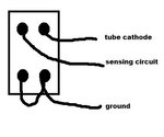
If anyone has any schematics or informantion on how the circuit works (there are 4 connections, rather than the usual 2), please PM me.

If anyone has any resouces let me know.

thanks.
 
I doubt anybody around here can help you because the guys that own engls around here never have any issues or problems.


Btw on hcaf I posted some info for you about this issue.
 
ZOMBIELAND":chwb2a24 said:
I doubt anybody around here can help you because the guys that own engls around here never have any issues or problems.


Btw on hcaf I posted some info for you about this issue.


Do u have a phone# or website
 
He has the switch wired wrong or he messed something up on the board. The standby switch lifts the ground to the power tube cathodes and the power tube monitor circuit. The switch has 3 wires, one is the ground supply, and the other two go out to the monitor circuit and the power tube cathode. There is also a jumper wire on the switch for the ground supply.
Jerry
 
baron55":28t7s2jz said:
On the powerball schematic I have, the Standby Switch grounds the cathodes of the power tubes when the amp is operational. But the schematic shows on the 2 connections. It could be (and I am speculating here) that on your version, the standby switch grounds each pair of power tubes cathodes to ground. And one side of the switch is shorted or both giving your power tubes power.

On many amps, the standby switch supplies the high B+ power supply to the entire amp. Although the current is very low, the voltage is very high.

In the ENGL design, the entire amp has high voltage supplied at all times. The Standby switch simply turns the power tubes on or off. The reason for this, is probbaly to eliminate high voltages at the switch, because the cathodes have relatively small voltages on them.


Cathodes are switched because there is less current thru the switch doing it that way. Ever measured the cathode voltage on a power tube when the groiund is lifted? It's not zero anymore.
Jerry
 
HI guys, appreciate the tech dialogue !!!

I am keeping these commnets to give to tech!

Thanks so far! :thumbsup:
 
baron55":qlnfob03 said:
JerryP":qlnfob03 said:
baron55":qlnfob03 said:
On the powerball schematic I have, the Standby Switch grounds the cathodes of the power tubes when the amp is operational. But the schematic shows on the 2 connections. It could be (and I am speculating here) that on your version, the standby switch grounds each pair of power tubes cathodes to ground. And one side of the switch is shorted or both giving your power tubes power.

On many amps, the standby switch supplies the high B+ power supply to the entire amp. Although the current is very low, the voltage is very high.

In the ENGL design, the entire amp has high voltage supplied at all times. The Standby switch simply turns the power tubes on or off. The reason for this, is probbaly to eliminate high voltages at the switch, because the cathodes have relatively small voltages on them.


Cathodes are switched because there is less current thru the switch doing it that way. Ever measured the cathode voltage on a power tube when the groiund is lifted? It's not zero anymore.
Jerry


My meaning was when the switch was closed, you don't have high voltage flowing through it. But most of the current in the B+ is power tube draw anyway. Just another way to skin a cat.

Peavey switches the screens on many of their amps, which are much lower current.

Voltage doesn't flow, current does. Any current on the B+ side of the power tube will be on the cathode side too, it's a complete circuit when the switch is closed. Peavey doesn't switch the just the screens, they switch all the B+ after the plates. Just a little further down the line than the typical way of doing it.
Switching the cathode allows less current draw thru the switch because you're only seeing the power tube draw and not the entire B+ circuit or the surge of filter caps charging.
Jerry
 
HI Guys,

The tech(s) I am dealing with state that the standby switch has 4 leads off it, not 2. They need some info on what all these leads do or any other info on them.

Please help if you know, I beg you.

:confused:
 
deadwrong666":3rujs4lj said:
HI Guys,

The tech(s) I am dealing with state that the standby switch has 4 leads off it, not 2. They need some info on what all these leads do or any other info on them.

Please help if you know, I beg you.

:confused:

Read Jerry from FJA's first response. He explained what the four wires do and that they must be wired out of order.
 
Why not contact an Engl service center. You are in Canada, right? They can contact Alex at Engl if they need support.

Musique Gagne & freres 302 Rue Durocher Quebec QC CAN 418-525-8601
 
Ive been trying to get the amp fixed for 4 months now, and the tech has been dealing or try to deal with Germany, there are not many others than can help, believe it or not.
 
Loudness250":7b186r97 said:
deadwrong666":7b186r97 said:
HI Guys,

The tech(s) I am dealing with state that the standby switch has 4 leads off it, not 2. They need some info on what all these leads do or any other info on them.

Please help if you know, I beg you.

:confused:

Read Jerry from FJA's first response. He explained what the four wires do and that they must be wired out of order.

Jerry mentions 3 wires, or am i misreading that?
 
4 wires all together. There is one jumper on the switch.
Jerry
 

Attachments

  • engl.jpg
    engl.jpg
    13.8 KB · Views: 1,154
JerryP":3bkqp776 said:
4 wires all together. There is one jumper on the switch.
Jerry


Thanks Jerry, I dont know what else these guys need to make this work. :doh:
 
JerryP":189p5wvh said:
He has the switch wired wrong or he messed something up on the board. The standby switch lifts the ground to the power tube cathodes and the power tube monitor circuit. The switch has 3 wires, one is the ground supply, and the other two go out to the monitor circuit and the power tube cathode. There is also a jumper wire on the switch for the ground supply.
Jerry
there is also a jumper wire on the switch to the ground supply, makes 4 right?
 
I have an SE. EVERY time a power tube goes bad it takes out one of the relays associated with the standby switch. This happened to the previous owner of the amp, me, and I have a friend with a Fireball who has had the same problem twice. On the powerball schematic: http://www.houseofenglamps.com/ENGL_Sch ... ematic.pdf

RE12, RE13, RE14, and RE15 are the culprits. I had my amp open a few weeks ago and the problem was very obvious, one of these relays had a hole burnt in it!!! The symptoms weren't the same as yours, my amp wouldn't come out of standby. But it's something to look into. I replaced all 4 for good measure. The 4.7 ohm resistor next to the relay was also bad.

I suppose it's possible that one of these relays is stuck in the closed position and keeping your tubes operational when in standby. I dunno, maybe Jerry will validate this as a possibility for me? I'm no amp tech, just good with electronics and soldering irons. I have A LOT to learn about amps!!!
 
I don't think his problem is the relays. His problem is the opposite of what you described, his amp won't go into standby. This amp has a power tube sensing circuit that will turn off individual power tubes if they draw too much current. There are two relays per tube, one in the sensing circuit which controls another one for the power tube cathode. The power tubes can be turned off two ways, one by the sensing circuit or by the standby switch. Actually three ways if you count the main power switch. If the amp had no output or a power tube that didn't have output then maybe the relays. His amp never turns off except with the main power switch. My first guess is the standby switch is wired wrong so it's not taking away the power tube cathode ground when switched or the cathode ground circuit of the circuit board is wired wrong and always connected to ground.
It's really a simple thing and the tech needs to re-check his wiring.
Jerry
 
I dont think I'm giving away secrets, but Engl Switchs' have been KNOWN to have problems... Seriously. had some last minute issues with shit turning on/off on a few we sold. a KILLER amp line, just occasionally not very 'switch' friendly..... :lol: :LOL: I believe, sir, that its a warranty issue... Demand a replacement switch... Nicely.... in German.
 
Gainiac":613cbgo9 said:
I dont think I'm giving away secrets, but Engl Switchs' have been KNOWN to have problems... Seriously. had some last minute issues with shit turning on/off on a few we sold. a KILLER amp line, just occasionally not very 'switch' friendly..... :lol: :LOL: I believe, sir, that its a warranty issue... Demand a replacement switch... Nicely.... in German.


I am beyond the warranty, besides, there wouldnt be warranty on how this all went down anyway.
 
Back
Top