Chase42147
Active member
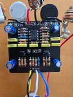
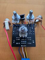
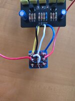
So I bought a PedalPCB Uberdrive (SD-1 style overdrive) about a year ago, and it didn't work the first time around. I got a nasty sound when I plugged it in, and shelved it for a year. Yesterday I pulled it out of the box to give it another go. I realized I missed one jumper cable on the on/off switch... And then I noticed I had soldered the tip contacts on the input and output jacks to ground. Reversed the wires on the jacks and now I at least get signal through the pedal. I have two problems now.
1) The gain pot doesn't do anything at all.
2) I get a noticeable volume drop when I engage the pedal. I don't have the on/off indicator LED installed, I'm guessing that doesn't affect anything. I'd install it but I have to clear solder out of the holes first. Also, I used 2SC1815 transistors instead of 2SC732's, as I couldn't find the latter. According to my research that's an acceptable substitution, but I could be wrong. If anyone could point me in the right direction that would be awesome