Peavey connector probs...

  • Thread starter Thread starter TJSlice
  • Start date Start date
TJSlice

TJSlice

New member
Hey all, posted this on HC VTM Lounge also... So I had my VTM60 apart to do a cap job and gain 2 switch mod, and even built a new headshell for the amp. All is good, but................ When I went to pull the molex connectors for the power supply board, one of the wires pulled out of the connector. So I fixed that up, put it all back together.

At the practice space the amp fires up, but a few small problems come up. The standby light stays on whether its on standby or not (it does go into standby though). And it seems to have less gain than before with all the switches off, so I know its not the mod. The tubes also don't seem to light up/put off as much heat as before....


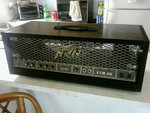
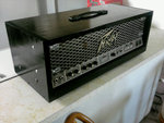
Is it possible the molex connector isn't making a good connection now, or that I put it on 180 degrees? I'm thinking of also hardwiring and ditching the molex connectors, so does anyone know which colors go to which post on the board so I can double check? Thanks a bunch..... And here is the new headshell, if anyone is interested. Kind of a ghetto job, but it serves its purpose :rock:
 

Attachments

  • Photo0231.jpg
    Photo0231.jpg
    252.2 KB · Views: 534
  • Photo0232.jpg
    Photo0232.jpg
    224.1 KB · Views: 530
What did you use to crimp the new connector, just some pliers or some wire strippers? Hopefully you used the actual crimp too for the connector, if not, than it sounds like a bad crimp. Using pliers to crimp a connector, we refer to as 'Mash and Bash', not the way to go for a good reliable crimp, though I have been guilty of doing this in the past.

Can you get a schematic for the amp somewhere? That should help you with wire colors to know you have it right....
 
Did a mash and bash, but I also soldered it too :yes: , as I don't trust it just being pinched in there. Here is a link to the schem http://www.schematicheaven.com/newamps/peavy_vtm_120.pdf. I think I could figure it out, but I suck at schem reading, so if anybody could label/mark the color to the pin where it relates to diagram on the pdf, I would crap myself in joy :D .
 
Do you have any pics of the modular connector and where it plugs in to? Usually, on a lot of these type of connectors, there will be a 'tell' of some sort as to which way is correct.
 
Might be a day or so before I can bring the amp back to the house. I remember all the connectors being designed to only go on one way, EXCEPT for J3 and J2 (the top 2 connectors) on the PS board.
 
Hazarding a guess, the connector on J2 may be backwards. The switch opens up to keep the power from coming through. If the standby light (or not on standby anymore light :D ) is on all of the time, that suggests that the power is being fed in backwards. So even with the switch open, the light will stay on. Whether or not that will cause the problems you are having, I don't know 100% for certain.

On J3, that looks like it comes from the PT, and the wires are possibly the same color? If it is the two sides of the AC line, and looks to be before rectification, I don't know that it will matter which way it goes. I did see the innards of a VTM power board, but the layout looked a little different from what I could see of it. I did notice that the Molex connectors were flat on one end, but rounded/pointed at the other. Typically, the rounded end is going to be Pin 1. That is one of the 'tells' I was curious about. Sometimes it's a notch, or a ridge, or something like the angle/rounded end that denotes Pin 1.

That's just a blind, somewhat educated, guess based on how that type of connector is usually made. I work on some telco equipment that is at the edge of obsolescence and with no schematics nor documentation, and I can usually get a better idea once I get eyes on the hardware.
 
Thanks for the replies guys. I'm probably gonna grab it tomorrow and bring it to the house to crack it open and have a look see.... At practice tonight the volume kept fluttering slightly, turned out it was the compressor circuit off the mod board is acting up, so I left it off. Which kinda made my tone not as "heavy", but it made up for it in the fact that it sounded quite a bit more RAW, so I might not worry about getting that looked at right off the bat.


O, and after a recap, is there a break in period of some sort? I know caps have to "form", but do they have a period where the character of an amp will be changing slightly until it gets settled in?
 
I have heard that caps do have a break in time, not really sure why this is though.

Its too bad that schematic does not have wire colors, but I think Jet66 is on the right track after looking at it myself....
 
Back
Top