PI grid leak resistor values

ledvedder

Well-known member
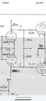
What effect would lowering the value of these resistors do? These are often referred to as grid leak resistors, correct?
FB_IMG_1670203240192.jpg
 
The PI grid leak resistors people typically refer to are actually the 150K in your schematic with an "RG" next to them that feed into the grid of the power tubes. Maybe that's what you're actually asking about? I would leave those 1M alone,
 
Those 1M are providing localized feedback into each grid and are a part of how a long tail pair phase inverter is designed. You leave those alone if you want the phase inverter to function correctly.

@FourT6and2 is correct in that the RG resistors are the grid leaks everyone speaks of. They change how the bias voltage responds to keep the power tubes throttled into class AB at idle. The tubes want to run wide open full throttle and the bias keeps them under control. As you play the tubes want to swing from plate voltage to ground but really swing class A to class AB in opposite phase pairs (in 100W amps, two tubes amplify 0 degrees and two amplify 180 degrees). Their quiescent operating point at idle is based on the plate voltage referenced to whatever potential is attached to the cathode (usually ground for fixed bias). As you change those resistors think about it as a super touchy throttle on your car versus a sluggish one. Just know power tube stability is a big deal and redplating tubes even under fractions of a second is hard on a lot of components other than the tubes themselves. If you have a solid understanding of the limits you can tweak them then it’s worth investigating but otherwise it’s better to leave them near stock values and not tweak too far off.
 
Last edited:
Those 1M are providing localized feedback into each grid and are a part of how a long tail pair phase inverter is designed. You leave those alone if you want the phase inverter to function correctly.

@FourT6and2 is correct in that the RG resistors are the grid leaks everyone speaks of. They change how the bias voltage responds to keep the power tubes throttled into class AB at idle. Think about it as a super touchy throttle on your car versus a sluggish one.
OK, I was just wondering what the differences would be in my Origin 20, which is cathode biased with power scaling. It originally had 470k in those spots. Then I modded the amp to a plexi, which involved changing them to 1M. Now I've redone it to a JCM800, so I was wondering what effect putting them back to 470k would have.
 
Last edited:
Naylor uses 560k in those spots instead of 1M.

I've tried lower values than 1M there. It'll reduce the gain of the amp and sound brighter/ more open. I still use 1M, but you asked what it'll do and that was my experience.
 

Attachments

  • E7D198AC-2661-4487-80B7-9AE15AC03224.png
    E7D198AC-2661-4487-80B7-9AE15AC03224.png
    1,013.9 KB · Views: 47
Last edited:
What is the technical term for these resistors?

They’re still called grid leak resistors because they take an idle bias voltage (created by the sum of two cathode currents) and feed back the voltage to each grid. The bias point is determined based on the B+ voltage and type of dual triode tube that’s used.

They’re a part of how phases are created for amplification for the power tubes, so normally they aren’t changed (and if they you you adjust them in pairs grid leak 1 = grid leak 2)
 
You can make those asynchronous. In the Dirty Shirly, Dave uses a 470k on the left side, and a 1M on the right.

Untitled.jpg
 
What effect does that have?

It's been a few years since I last built a DS clone. I played with the standard 1M/1M, and then the 470k/1M, I ended up liking the 470k/1M

It was subtle, but I think it was more lively IIRC

You can just parallel another 1M in with some alligator leads to test whether you like it or not.
 
What effect does that have?
It reduces the amount of duty-cycle modulation that occurs when overdriving the phase inverter. Typically, values in the range of 330k to 390k give the best results, but 470k may be enough. It will not affect the normal, non-overdriven PI balance of the two sides.

Duty-cycle modulation creates even-order harmonics and adds a dynamic feel to overdrive that changes with how hard you hit it.

Normally, this is a good thing, all old non-master Marshalls do it, some to a greater extent than others, and is an important part of the sound and feel.

However, this asymmetrical overdrive means that one side of the output stage is driven harder than the other, and sometimes this results in redplating of only one tube in a 50W or pair of tubes in a 100W amp.

This can be avoided by designing for a proper reflected load impedance of the output transformer and designing in the proper amount of sag in the power supply to keep the tubes out of the 2x dissipation curve under heavy overdrive.

Since this is difficult to change after an amp is designed, reducing the amount of duty-cycle modulation can prevent one-side redplating, at the cost of loss of dynamic harmonic feel in heavy overdrive.

Even if you don't have a one-side redplating issue, you may prefer a more symmetrical overdrive, so you can play with the value of that grid bias reference resistor and adjust to taste. Personally, I love the duty-cycle modulation and do not like a more balanced overdrive, it results in only odd-order harmonics and sounds thinner and less dynamic to my old ears.

In an amp that has a pre-phase inverter master, and/or if you don't drive the amp to output stage clipping, the effect is much more subtle. Reducing the value of the input side grid reference resistor raises the cutoff frequency of the low pass filter formed by the input coupling capacitor and that resistor, resulting in less low end and a tightening of the tone. Since the PI effectively bootstraps the circuit, the actual effective input resistance is much higher than the resistor value, typically around 4x, so you can get by with lower values without affecting the low end too much, especially considering the input coupling capacitor value is usually way higher than needed.

The RC time constant also affects the dynamic transient response, so there are a lot of interactive things going on.

Best to use your ears to determine what you prefer, unless you are trying to prevent or solve an asymmetric redplating issue.
 
Last edited:
This can be avoided by designing for a proper reflected load impedance of the output transformer and designing in the proper amount of sag in the power supply to keep the tubes out of the 2x dissipation curve under heavy overdrive.

The valve rectifier in the DS probably helps mitigate this. Although the last one I did like this was a 50w SS rectifier, and tubes have been fine for last two years. That being said, I'm usually setting the bias on these gainey amps much cooler.
 
Everything above sort of explains why I went back and forth between 1M and 500k (two 1Ms in parallel) for that input grid leak to the PI in my Superlead.
 
It was a sequence of mods that went almost full circle and ended up with 1M again. I ran with 500k for a while and actually forgot about it. It did clean up some rattiness in the distortion but after I cleaned that up elsewhere the 1M sounded right again.
Yeah I can comment on that too. I had a recent ratty sound that stuck out in a recording and once I heard it in a recording, I couldn’t un-hear it in person. I traced it down to a single capacitor that was the cause earlier in the preamp. I’ve not messed with the 1M values - to me if they need adjustment it likely can be done elsewhere first and more efficiently. I rather keep tonal chances out of my PI unless I was building for the whole post PPIMV pushed PI sound which I’m personally not chasing.
 
Best to use your ears to determine what you prefer, unless you are trying to prevent or solve an asymmetric redplating issue.
I built a Brown Deluxe that was red plating one side but those use a 6k8 tail. Increasing it to 10k seemed to balance it enough to not redplate. I may have also replaced a drifted cc PI plate resistor. Is there a preferred method to balance the PI? The Naylor PI posted earlier had 560k grid resistors but both plates were 100k. These all probably have their own side effects and is perfect balance even what we want? This is wrt Marshall PIs.
 
I built a Brown Deluxe that was red plating one side but those use a 6k8 tail. Increasing it to 10k seemed to balance it enough to not redplate. I may have also replaced a drifted cc PI plate resistor. Is there a preferred method to balance the PI? The Naylor PI posted earlier had 560k grid resistors but both plates were 100k. These all probably have their own side effects and is perfect balance even what we want? This is wrt Marshall PIs.
Note that we are talking about two very different things here, balance in normal operation, which is designing the circuit for equal amplitude signals on the two outputs when the PI is npt overdriven, and duty-cycle balance when the PI is overdriven, to prevent asymmetrical drive to the output stage in order to limit one-sided redplating.

The best way to balance a PI for normal operation is with a true constant current source in the tail, but this requires extra circuitry, usually solid-state stuff that people don't want in a tube amp.

The tail resistor emulates a constant current source to a certain extent. Making the tail resistor larger makes it act as a better constant current source, but at the expense of reducing headroom in the PI due to the extra voltage drop across the larger tail resistor, so there is a practical limit to how large you can make the tail.

The reason the plate resistors are mismatched at 82k/100k in a typical Marshall PI is because the 10k tail resistor is not enough of a constant current source to fully balance the PI, so the two phase amplitudes have to be balanced by using different plate load resistor values.

Once the PI is heavily overdriven, especially without a true constant current source tail, the normal balance goes out the window, so you have to resort to other methods to balance the duty cycle modulation, if that is your goal.

Redplating occurs not because the PI design is bad, but because the output stage was not designed correctly to handle asymmetrical overdrive, due to too high a plate voltage with not enough sag and/or incorrect reflected primary impedance for the plate voltage used. Designing for overdriven output stages requires a bit of extra effort to keep tube operation below the 2x max dissipation curve on the load line for each side of the push-pull pair. You can actually run right up to twice the max dissipation curve because each side only conducts for half the time, so it averages out to 1x max dissipation. Of course, this changes with duty-cycle modulation, so you have to take that into account.
 
Last edited:
IMHO: Changing one of those grid resistors from 1M to 470k changes the operating point of the PI tube negligibly and thus the symmetry of the PI negligibly. In simple terms, these resistors only raise the cathodes against the grids by the voltage on the 470 Ohm resistor, and within certain limits their size does not matter. In a way, the asymmetry of the units in the tube has a bigger influence. You change the tube and everything is a little bit different. However, the size of these resistors determines the input impedance of the PI, which is why the character of the sound can change. Rather, let's talk about the value of the anode resistors, which have a fundamental effect on the symmetry of the PI.
 
Back
Top