Greetiings
")
I thought I had a recent photo of the completed tray, but I guess it's not on this computer. I'm not sure if this will be much help, but here you go. It was my first effort at building and cabling a rack...
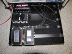
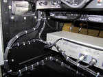
Photo 1:
Shows some of the pedals in the position they will be in when the tray is completed (upside down so the Velcro won't stick...). The Pedal Power 2 is already fastened and I was just starting to get all of the wires cut to length and laid out neatly. I used Mogami W2319 cable (purchased from Redco) and Switchcraft #226 and #280 connectors (purchased from Best-Tronics)
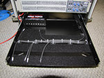
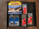
Photo 2:
A better view of the progress of getting the cables neatly organized and secured to the tray. I'm a little OCD
I taped labels to the end of each cable according to which loop they would connect to on the GCX for ease of re-placement since I intended to remove the bundle after dry-fitting so I could solder the connectors on a bench. I only had to snip the Zip Ties that were holding the bundle to the mounts; the other ties held the bundle together and made putting it back in much easier.
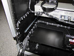
Photo 3:
A view from the rear of the rack showing the cable bundle. I was in the process of determining how much extra cable would need to be looped to allow the tray to be pulled out (and how I was going to route it)...
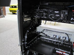
Photo 4:
A view of the service loop. There is enough cable to completely extend the tray, but the bundle is secured at both ends to minimize movement otherwise. Don't forget that you need to leave a service loop for the power cord to the Pedal Power (if you use one and have it on the tray...)
Hope this helps. If I find some more recent photos, I'll re-post...