question for amp builders/techs.

  • Thread starter Thread starter moltenmetalburn
  • Start date Start date
moltenmetalburn

moltenmetalburn

Active member
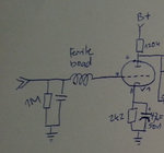
I have a preamp I am going to modify slightly for a different feel at the input.

This particular design has a "grid stopper" resistor first in line and then a small cap before the 1 meg to ground.

The amplifier I am emulating has a ferrite bead in the place of these two components.

Can I remove both and replace with only the ferrite bead as I see in so many other designs? any considerations?

have a source for the "correct" bead/size?, i have seen a few but not exactly sure what to get.


thanks! :rock:
 
Technically there is a desired input impedance that 12AX7 varieties prefer to see on the grid.

It's a spec based on the 1950's, and it prevents any oscillations from occurring due to tube manufacturing variations. It's also beneficial to keep some resistance because a tube will naturally pick up any radiation from nearby LOS radio towers.

The 1M resistor is part of the input impedance along with your guitar's volume pot as it is in parallel with this resistor. Do not change this as it affects the desired input impedance range for a 12AX7 and is already as high as it can go.

Personally I always make sure a 10k resistor is installed as close as possible to the grid (preferably right on the socket with short leads) of the first tube to minimize any damaging amplitudes from a guitar pedal, hot pickup, microphones, or transient static voltages. It won't hurt to keep the ferrite bead as well - it's tuned to shunt higher frequencies and won't have any ill effects for general low frequency audio. You should however consider having some resistance in series with the grid for the reasons mentioned above.
 
glpg80":221kdxfd said:
Technically there is a desired input impedance that 12AX7 varieties prefer to see on the grid.

It's a spec based on the 1950's, and it prevents any oscillations from occurring due to tube manufacturing variations. It's also beneficial to keep some resistance because a tube will naturally pick up any radiation from nearby LOS radio towers.

The 1M resistor is part of the input impedance along with your guitar's volume pot as it is in parallel with this resistor. Do not change this as it affects the desired input impedance range for a 12AX7 and is already as high as it can go.

Personally I always make sure a 10k resistor is installed as close as possible to the grid (preferably right on the socket with short leads) of the first tube to minimize any damaging amplitudes from a guitar pedal, hot pickup, microphones, or transient static voltages. It won't hurt to keep the ferrite bead as well - it's tuned to shunt higher frequencies and won't have any ill effects for general low frequency audio. You should however consider having some resistance in series with the grid for the reasons mentioned above.


thank you!

I actually have done some reading and at least loosely understood some of what you are describing above. the one caveat is id like it to be identical to the input i am using which does not meet these considerations.

Given your knowledge ill be specific. I have a vht valvulator i want to mod to match the input of the amp i use it with. they are different. its like stacking a rock amp feel over a high gain channel. odd.

will I reach my desired result buy simply change the resistor values to match and leaving the grid stopper/cap in place instead of replacing both with a ferrite bead and no grid stopper?
 

Attachments

  • Input.jpg
    Input.jpg
    49.3 KB · Views: 539
You're welcome :)

What you have drawn is a crude combination of two types of low pass filters.

A series inductor (ferrite bead) is one type of low pass filter, and a series resistor with the capacitor in parallel is another type (inductors have a small inherit resistance). Physically defining a series resistor serves a multitude of purposes as explained earlier. You can remove the capacitor all together in that setup and tune the ferrite bead - unless you're including the capacitor for some personal tonal preference. You could also remove the ferrite bead and tune the capacitor to some physical resistor.

I'd still recommend the capacitive low pass filter utilizing a physical resistor in series with the grid. A metal film resistor around the range I spoke of will have very little to do with the feel or tone of your amplifier, will suppress transient voltage problems as mentioned in the previous post, and as far as ideal resistors are concerned they are linear with respect to frequency and amplitude, as only heat will change that.

Let me know what you plan to do and change from here and I can help :)
 

Similar threads

Back
Top