Amp Build: Cameron Aldrich

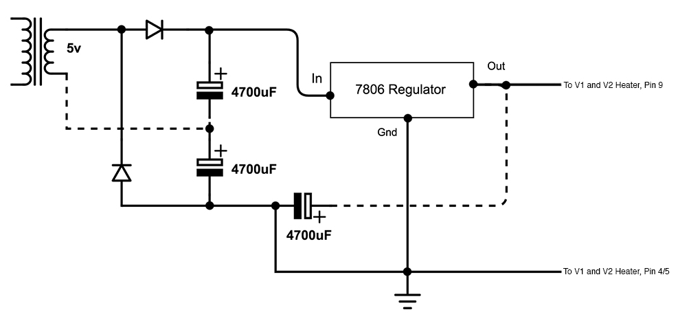
How are your DC heaters for V1/V2 hooked up? Looks like you have pin 9 blank? And then a separate line to pins 4/5? I've always implemented DC heaters differently because I'm using Ceriatone's DC heater board which regulates differently I think? And they have there's with pins 4/5 on each socket grounded and pin 9 is getting the source DC feed. But I'm running 6v DC and you're using 12v.

dc_heaters_by_haftelm-dbax34w.jpg
 
Pin 4 DC +12v, pin 5 DC 0v. (Well in theory :LOL: :LOL: ) You can see the same heater layout for the DC on Friedman amps.

Going to take down the heater board, verify my connections on the transformer taps, verify the voltage on the taps, and move the voltage regulator to the chassis as soon as my thermal interface pads get here.
 
Reading these replies makes me giggle. It is like a foreign language and I have absolutely no idea what any of it means. Hopefully the amp finalizes itself and you come out happy.

This would be such an amazing skill to have (building amps)
 
maddnotez":iqhgv6e3 said:
Reading these replies makes me giggle. It is like a foreign language and I have absolutely no idea what any of it means. Hopefully the amp finalizes itself and you come out happy.

This would be such an amazing skill to have (building amps)

Don't worry, I have no clue what I'm talking about. Just faking it lol. TWENTY-THREE VOLTAGES OFF PIN SIX FOR REVERSE BREAKDOWN AMPS. IMPEDANCE!!! SOMEONE GET ME A BYPASS RESISTOR TO COUPLE THE FLUX CAPACITOR. STAT!
 
FourT6and2":i6hgv4if said:
maddnotez":i6hgv4if said:
Reading these replies makes me giggle. It is like a foreign language and I have absolutely no idea what any of it means. Hopefully the amp finalizes itself and you come out happy.

This would be such an amazing skill to have (building amps)

Don't worry, I have no clue what I'm talking about. Just faking it lol. TWENTY-THREE VOLTAGES OFF PIN SIX FOR REVERSE BREAKDOWN AMPS. IMPEDANCE!!! SOMEONE GET ME A BYPASS RESISTOR TO COUPLE THE FLUX CAPACITOR. STAT!

Exactly :LOL: :LOL:

Also that annoying moment when the only part you don't have is the one that likely won't show up until next week (I don't have a thermal interface for the voltage regulator)

Never fear I'll get it working, I have too many parts laying around to give up now :LOL: :LOL:
 
technomancer":3bzxlxfm said:
FourT6and2":3bzxlxfm said:
maddnotez":3bzxlxfm said:
Reading these replies makes me giggle. It is like a foreign language and I have absolutely no idea what any of it means. Hopefully the amp finalizes itself and you come out happy.

This would be such an amazing skill to have (building amps)

Don't worry, I have no clue what I'm talking about. Just faking it lol. TWENTY-THREE VOLTAGES OFF PIN SIX FOR REVERSE BREAKDOWN AMPS. IMPEDANCE!!! SOMEONE GET ME A BYPASS RESISTOR TO COUPLE THE FLUX CAPACITOR. STAT!

Exactly :LOL: :LOL:

Also that annoying moment when the only part you don't have is the one that likely won't show up until next week (I don't have a thermal interface for the voltage regulator)

Never fear I'll get it working, I have too many parts laying around to give up now :LOL: :LOL:

You talking about that little thermal pad? Meh. Fire the amp up without it then put it in when it arrives. It won't make a huge difference.
 
technomancer":18zhg6zm said:
That awkward moment when you power up and are reading 27v off of the 15v tap from the transformer...


Loaded, or not loaded? and before, or after rectification?

A 15vac 2amp tap will probably read around 19vac with no load. Then if you bridge rectify that 19 * 1.4 = 26.6vdc no load
 
CrazyNutz":2sbef6qu said:
technomancer":2sbef6qu said:
That awkward moment when you power up and are reading 27v off of the 15v tap from the transformer...


Loaded, or not loaded? and before, or after rectification?

A 15vac 2amp tap will probably read around 19vac with no load. Then if you bridge rectify that 19 * 1.4 = 26.6vdc no load

I suspect it was a measuring error on my part. I'm moving the voltage regulator to chassis mount regardless as the thing was too hot to touch which to me means a heat sink on it is a good idea. I'll follow up once I get things moved around.
 
technomancer":13yr1d8o said:
CrazyNutz":13yr1d8o said:
technomancer":13yr1d8o said:
That awkward moment when you power up and are reading 27v off of the 15v tap from the transformer...


Loaded, or not loaded? and before, or after rectification?

A 15vac 2amp tap will probably read around 19vac with no load. Then if you bridge rectify that 19 * 1.4 = 26.6vdc no load

I suspect it was a measuring error on my part. I'm moving the voltage regulator to chassis mount regardless as the thing was too hot to touch which to me means a heat sink on it is a good idea. I'll follow up once I get things moved around.

That hot? Wow. I should probably check mine.
 
technomancer":jroook58 said:
CrazyNutz":jroook58 said:
technomancer":jroook58 said:
That awkward moment when you power up and are reading 27v off of the 15v tap from the transformer...


Loaded, or not loaded? and before, or after rectification?

A 15vac 2amp tap will probably read around 19vac with no load. Then if you bridge rectify that 19 * 1.4 = 26.6vdc no load

I suspect it was a measuring error on my part. I'm moving the voltage regulator to chassis mount regardless as the thing was too hot to touch which to me means a heat sink on it is a good idea. I'll follow up once I get things moved around.

Ok since I am working from home I said screw it and did some measuring :LOL: :LOL:

I think the voltage regulator is just overheating after a few seconds and going into shutdown as I am reading 12v on the heaters of both tubes and then after a few seconds it starts to fall off. AC heaters are right around 7v on the PI which is with no load and no power tubes so not weird. I'm going to swap out the voltage regulator and mount it to the chassis as a heatsink and see if that straightens things out.
 
FourT6and2":2ut4thnw said:
technomancer":2ut4thnw said:
CrazyNutz":2ut4thnw said:
technomancer":2ut4thnw said:
That awkward moment when you power up and are reading 27v off of the 15v tap from the transformer...


Loaded, or not loaded? and before, or after rectification?

A 15vac 2amp tap will probably read around 19vac with no load. Then if you bridge rectify that 19 * 1.4 = 26.6vdc no load

I suspect it was a measuring error on my part. I'm moving the voltage regulator to chassis mount regardless as the thing was too hot to touch which to me means a heat sink on it is a good idea. I'll follow up once I get things moved around.

That hot? Wow. I should probably check mine.

I'm getting a steady ~22.4v DC coming off the rectifier so it is something after that and since it is rock steady at first then flakes out the regulator is my best guess as it looks like it runs at 12v steady than drops or cuts out and comes back up and gets worse as time goes on.
 
Yeah, you must run a heatsink (or chassis sink) on that regulator. Your DC after the rectifier (22.4), and filter cap is in range 15 * 1.4 = 21vdc

21vdc (or 22.4 in your case) to 12vdc is a lot of power to dissipate, the regulator without a heat sink will be blazing.
 
CrazyNutz":jolxiz29 said:
Yeah, you must run a heatsink (or chassis sink) on that regulator. Your DC after the rectifier (22.4), and filter cap is in range 15 * 1.4 = 21vdc

21vdc (or 22.4 in your case) to 12vdc is a lot of power to dissipate, the regulator without a heat sink will be blazing.

Yep I was dumb and only considered the draw on the regulator vs capacity not dissipation from the input. Live and learn... and rewire :LOL: :LOL:
 
Back
Top