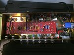
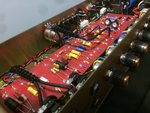
Just received my new Suhr SL67. Amazing amp! As I really appreciate a quality build(and this is quality folks!) I had to take it out of it's chassis to have a look at the internals and noticed two, what looks like, bias pots. I am no electrician by any means but have biased Marshalls in the past. Not that I feel the need at the moment to re-bias and sorry if it's completely obvious, but where do I put the probs on this board to measure the BIAS. I have attached a pic for reference. In the second pic you can see them at the top right, like two eyeballs staring at you.
You are using an out of date browser. It may not display this or other websites correctly.
You should upgrade or use an alternative browser.
You should upgrade or use an alternative browser.
Suhr SL67 - Biasing Tubes
- Thread starter Edit321
- Start date
SpiderWars
Well-known member
It looks like there are current-measuring resistors on the cathodes of the power tubes. It's those little brownish resistors that connect to the standoffs right next to the sockets. They should connect to pins 1 and 8 on the power tube sockets. If they are the common 1ohm resistors then 1mV measured across that resistor equals 1mA of current (for that tube only). You'll also need to measure the plate voltage on the power tubes (pin 3).
If you want to measure the actual bias voltage you can measure that at pin 5 or on that PPIMV on the outside lug that has the resistor soldered to it. Or back at bias supply on the board. You can measure that with the amp on Standby but it often changes a tiny bit once the amp is ON.
You can measure the value of those cathode resistors on the power tubes by measuring across them with the amp OFF and unplugged, make sure they are 1ohm before you do any calculations. Just make sure you switch your meter back to 'voltage' before doing the other measurements.
One of those adjustment pots is to adjust the range of the bias supply (to use different tube types usually) and the other is for the typical adjustments once you've decided what tube type you want. Usually you would adjust the one that has one lug connected to ground (most likely the one closest to front of amp) but in reality you can use either one.
Cool amp!
SpiderWars":5htn1l3j said:It looks like there are current-measuring resistors on the cathodes of the power tubes. It's those little brownish resistors that connect to the standoffs right next to the sockets. They should connect to pins 1 and 8 on the power tube sockets. If they are the common 1ohm resistors then 1mV measured across that resistor equals 1mA of current (for that tube only). You'll also need to measure the plate voltage on the power tubes (pin 3).
If you want to measure the actual bias voltage you can measure that at pin 5 or on that PPIMV on the outside lug that has the resistor soldered to it. Or back at bias supply on the board. You can measure that with the amp on Standby but it often changes a tiny bit once the amp is ON.
You can measure the value of those cathode resistors on the power tubes by measuring across them with the amp OFF and unplugged, make sure they are 1ohm before you do any calculations. Just make sure you switch your meter back to 'voltage' before doing the other measurements.
One of those adjustment pots is to adjust the range of the bias supply (to use different tube types usually) and the other is for the typical adjustments once you've decided what tube type you want. Usually you would adjust the one that has one lug connected to ground (most likely the one closest to front of amp) but in reality you can use either one.
Cool amp!
Thank you for the detailed response! I will check this out!
One of those adjustment pots is to adjust the range of the bias supply (to use different tube types usually) and the other is for the typical adjustments once you've decided what tube type you want. Usually you would adjust the one that has one lug connected to ground (most likely the one closest to front of amp) but in reality you can use either one.
Cool amp![/quote]
WRONG WRONG WRONG, these amps have 2 Power settings ( High and Low ), and those bias pots are for each power setting. The amp only works with EL34 tubes and each bias pot lets you adjust for each power mode..
Cool amp![/quote]
WRONG WRONG WRONG, these amps have 2 Power settings ( High and Low ), and those bias pots are for each power setting. The amp only works with EL34 tubes and each bias pot lets you adjust for each power mode..
QOTSA_Lover
New member
Nope. One BIAS for the HI and one for the LOW Setting on the STBY Switch.