You are using an out of date browser. It may not display this or other websites correctly.
You should upgrade or use an alternative browser.
You should upgrade or use an alternative browser.
1974 120W SL/A Restoration Project v2.0
- Thread starter glpg80
- Start date
glpg80
Well-known member
SpiderWars":1bwqtltu said:The few amps/schematics I've seen that use DC for the heaters typ only use it for V1 and sometimes V2 (I've never done it, I've only lifted the CT). Is there a specific reason for DC heaters for the PI or is it just a matter of; "12vdc is now available, might as well use it"? Or maybe current-handling issues if running more than 1 or 2 tubes? I noticed Ceriatone uses 7812 regulators for V1/V2 but there appears to a 14v tap on the PT.
Usually the first few stages are done because of the principals of the noise figure equation. The noise floor is set by the gain of the first stage and every stage after that has an inverse proportionate factor in overall system noise. So if you can eliminate as much noise in the first few stages, the rest of the system doesn’t require it. Additional reasons for not supplying DC to the power tubes is that these are class AB power amplifiers which cancel mutual coupling sources such as cascaded noise.
The reason I’m supplying DC to the phase splitter as well is because your noise floor is directly related to how well each triode is matched, and any mismatch which also has capacitive coupling of heater noise to the cathodes of the envelopes can contribute to the noise floor as well as phase noise as it’s used for phase splitting of the original signal.
Another reason people don’t do it is that dc heaters require a lot of power and you need a stout supply to handle initial current surges. It’s a cost thing if anything else. Additionally DC heaters not done correctly can actually cause more noise because of ripple riding on the DC from poor filtering.
glpg80
Well-known member
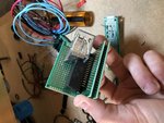
Finished building my bias control daughter board. Next I have to grab some much needed bench equipment to do some testing before final installation.
I plan to move onto the power control board next, followed by the relay control board for footswitchable features.
I plan to move onto the power control board next, followed by the relay control board for footswitchable features.
Attachments
glpg80
Well-known member
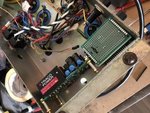
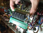
Spent some time this week putting together and starting the power control board. Mounting the relay had some challenges as there wasn’t enough room to use a snap in type and the through hole pitch was different than my prototype boards available. I managed to make it work and I am happy with the results. It should lend itself to be fairly easy to repair and replace when the time comes.
Right now I have bench equipment inbound for testing the bias design. Next I need to order a digital oscope to confirm my fly back snubber circuit for the relay works as intended. If you’re not careful the relay coil will generate a large voltage spike on the primary which is then stepped up to thousands of volts on the secondary, wiping out diodes and capacitors. A digital scope is needed to confirm the inductive flyback is controlled successfully.
Right now I have bench equipment inbound for testing the bias design. Next I need to order a digital oscope to confirm my fly back snubber circuit for the relay works as intended. If you’re not careful the relay coil will generate a large voltage spike on the primary which is then stepped up to thousands of volts on the secondary, wiping out diodes and capacitors. A digital scope is needed to confirm the inductive flyback is controlled successfully.
Attachments
glpg80
Well-known member
SpiderWars
Well-known member
Looks good! That pic made me just realize a 2204 I just bought looks like it may have had DC heaters because it had those ground tabs at V1 and V2 (now unused since the amp had been restored to stock).
Does AC vs DC heaters affect twist vs no twist? Some amps like Soldanos don't twist at all.
Does AC vs DC heaters affect twist vs no twist? Some amps like Soldanos don't twist at all.
glpg80
Well-known member
SpiderWars":1rahz7vp said:Looks good! That pic made me just realize a 2204 I just bought looks like it may have had DC heaters because it had those ground tabs at V1 and V2 (now unused since the amp had been restored to stock).
Does AC vs DC heaters affect twist vs no twist? Some amps like Soldanos don't twist at all.
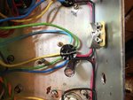
Thanks man! Some wires from before had the insulation burned from a soldering iron in the past and the wires have gotten stiff on this thing. I know for sure it’s original wiring but I’m replacing what’s burned or compromised as I go. It’s adding on a bit of time for sure.
I added the ground tabs of course so that I have a place to install my heater filtration caps.
AC is twisted to contain the B field. The theory is that the twist minimizes the amount of flux leakage as the currents in each wire oppose one another of the same magnitude, making a net B field that is much smaller. The more current through a wire the larger the B field around it so twisted heater wires on AC current is fairly important to minimize magnetic coupling.
DC doesn’t benefit from twisting because the currents are not alternating, but do benefit from being directly on top of one another for a net neutral cancelation of any mutual coupling from other AC wires. You still have to practice good wiring layout away from the plates and grids of the tubes to minimize magnetic coupling, but any coupling that exists on DC won’t be picked up as an audible 120Hz or 60Hz hum as is on AC heaters assuming of course no other parasitic coupling sources.
Cheers,
-Matt
glpg80
Well-known member
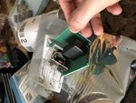
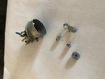
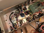
Was working on the amp over my lunch break and got to the last tube socket. One of the pins pulled out and I barely did anything - just moved a wire. It’s been pop riveted into the chassis and isn’t the same quality as the others - some Chinese made socket. It’s V1 in the amp and likely worn out from tube rolling. It looks like the work from the same person who did the other shady work.
Looks like I have to stop on the heaters and order a new replacement socket first.
Looks like I have to stop on the heaters and order a new replacement socket first.
Attachments
glpg80
Well-known member
I haven’t posted any real updates lately.
I needed the footswitch physically in my hands to test with my meter to see how it works as I didn’t understand it from the vague schematics shared online compared to amplifier schematics like the valvestate series.
So I reverse engineered the SPDT and built in LED status lights to see what my relays need wired to be for the correct function. I also want the amplifier to be in the correct relay state when the footswitch is unplugged (main master active and not the rear, effects loop enabled and not bypassed, etc etc) so that you don’t have to have it inserted to get correct operation as-is.
I also needed to ohm out the losses and factor that in to make sure my voltages don’t drop below relay minimums with all turned on.
I ordered and have received my new preamp tube sockets and have decided to change them all at once while I’m at it.
I’ve also been working on the bias board and have it installed in the amplifier. I have both bias pot holes drilled and mounted as well.
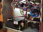
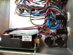
I mounted the standalone power supply to the chassis successfully.
I upgraded the wiring to the heaters to 18 AWG with a standoffs so that either the supply could be removed or the heaters worked on without affecting the wiring from one side of the chassis to the other for easier repair. This added some challenges as I still have to keep room for the effects loop.
The loop will have to be the very last thing installed because I have to get a B+ reading with the old tubes installed and biased so that the effects loop can then be biased correctly under load.
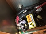
I also had a change in the design. I’m going away with my relay control board and decided to remove the original arrow Hart batwing switches in favor of new Marshall certified 20A 125VAC power and standby switches. I was concerned with flyback voltage spikes in parallel with the primary of the PT then being translated to a KV spike on the secondary taking out rectifier diodes.
When I have my schematics updated from the changes I’ll have to make based on what the footswitch needs, and sockets fully replaced, and the bias fully wired/connected, then I’ll post some updated pictures.
I needed the footswitch physically in my hands to test with my meter to see how it works as I didn’t understand it from the vague schematics shared online compared to amplifier schematics like the valvestate series.
So I reverse engineered the SPDT and built in LED status lights to see what my relays need wired to be for the correct function. I also want the amplifier to be in the correct relay state when the footswitch is unplugged (main master active and not the rear, effects loop enabled and not bypassed, etc etc) so that you don’t have to have it inserted to get correct operation as-is.
I also needed to ohm out the losses and factor that in to make sure my voltages don’t drop below relay minimums with all turned on.
I ordered and have received my new preamp tube sockets and have decided to change them all at once while I’m at it.
I’ve also been working on the bias board and have it installed in the amplifier. I have both bias pot holes drilled and mounted as well.
I mounted the standalone power supply to the chassis successfully.
I upgraded the wiring to the heaters to 18 AWG with a standoffs so that either the supply could be removed or the heaters worked on without affecting the wiring from one side of the chassis to the other for easier repair. This added some challenges as I still have to keep room for the effects loop.
The loop will have to be the very last thing installed because I have to get a B+ reading with the old tubes installed and biased so that the effects loop can then be biased correctly under load.
I also had a change in the design. I’m going away with my relay control board and decided to remove the original arrow Hart batwing switches in favor of new Marshall certified 20A 125VAC power and standby switches. I was concerned with flyback voltage spikes in parallel with the primary of the PT then being translated to a KV spike on the secondary taking out rectifier diodes.
When I have my schematics updated from the changes I’ll have to make based on what the footswitch needs, and sockets fully replaced, and the bias fully wired/connected, then I’ll post some updated pictures.
glpg80
Well-known member
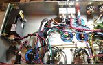
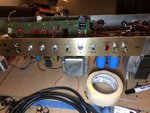
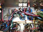
Making progress on my amp design. Disregard the wiring mess, nothing is cinched yet. Mains and standby power re-wired with upgraded switches, DC supply mains wired in, bias board designed and mounted, but still needs connection. New faceplate (other for sale in classifieds). Once the heaters are finished, I can switch over to the preamp and finish replacing the tube sockets along with completing the actual amplifier modifications. I also have the relay schematic designed but need to order more parts before assembly. Getting there!
Attachments
SpiderWars
Well-known member
Those switches look bombproof. Where did you source the cap cans? I'v never used those.
glpg80
Well-known member
SpiderWars":2hd07aib said:Those switches look bombproof. Where did you source the cap cans? I'v never used those.
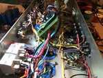
The caps are ARS. They're top of the line and as good as it gets. They're made in the USA and out of CA. I've used F&T in the past - I recapped a 1979 JCM800 Fawn I owned for a small length of time and they sounded good as well.
The DC supply needs 1.8A max, with a 3A internal overload breaker on both line and neutral both which also protects against ground and neutral fault as well as overcurrent on mains. The stock marshall switches aren't rated for that additional ampacity and would likely be welded in the ON state. The switches were also showing signs of corrosion from the vented Daly can capacitor that I replaced. The amp ran with 1 cap blown for an extended period of time before I owned it. In that state it proceeded to eat away by corrosion the original switch leads and the wires soldered to them as well. The switches still work and I will keep them, but they're not fit for use anymore IMO.
The switches in it now are the same ones in 1959HW reissues. They're basically milspec - welded contact connectors and rated to 15A @277VAC. They weren't cheap but will do the part to handle the current I'm throwing at it now. Both the DC and PT are off the stock 4A fuse that way if there's a fault with either the PT or the supply, the fuse will blow cutting the whole amplifier off. I also rewired it so that the PT goes through the fuse AND the switch before going to the windings which protects the PT and the user in case of a switch fault.
Unless there is a fault, the 4A fuse should be fine on the mains side as I'm not stressing the supply at all. However I will be measuring peak AC current when the time comes for initial turn on to rate it accordingly.
glpg80
Well-known member
Goat":2lqoptw9 said:Why are you converting the heaters to DC?
I needed 12V to power relays for footswitchable master volume for a solo boost, footswitchable metroloop bypass, and footswitchable HI/LO input for poor man's clean. The added benefit of having 12V DC is that I can also run all preamp tubes off of the DC supply after heavy filtering and get the noise down while also removing some stress from the original Dagnall PT. The PT is still supplying the AC heaters for the power tubes because in a class AB amplifier, any common mode noise is canceled through tube matching and bias. To go one step further, the AC heaters on the power tubes are getting lifted on the 12V DC as well to improve the heater to cathode voltage rating giving even more protection from noise.
glpg80":3q7re0pt said:Goat":3q7re0pt said:Why are you converting the heaters to DC?
I needed 12V to power relays for footswitchable master volume for a solo boost, footswitchable metroloop bypass, and footswitchable HI/LO input for poor man's clean. The added benefit of having 12V DC is that I can also run all preamp tubes off of the DC supply after heavy filtering and get the noise down while also removing some stress from the original Dagnall PT. The PT is still supplying the AC heaters for the power tubes because in a class AB amplifier, any common mode noise is canceled through tube matching and bias. To go one step further, the AC heaters on the power tubes are getting lifted on the 12V DC as well to improve the heater to cathode voltage rating giving even more protection from noise.
glpg80
Well-known member
glpg80
Well-known member
Small update, I’ve been working on designing the relay board. I’ve been searching for high quality wire connectors as I don’t want to solder the wires to the relay board. For starters you don’t want this as the more you move the board around with soldered wires, the more you ask for a broken connection. I’m sourcing some gold plated locking connectors so that the connections are good and won’t cause distress when installing it.
I don’t have anything to show for updates at the moment. Life has been getting in the way lately.
When I have the pins and connectors chosen and delivered, I’ll be able to assemble the relay board and the ball will start rolling again.
I don’t have anything to show for updates at the moment. Life has been getting in the way lately.
When I have the pins and connectors chosen and delivered, I’ll be able to assemble the relay board and the ball will start rolling again.
glpg80
Well-known member
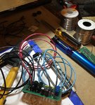
Was able to complete the bias board installation and connection, so that is now complete!
I also started the relay board layout while connectors are coming in
I also finally connected the indicator light.
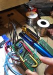
Still have two sockets to replace, it’s taking longer than I wanted due to the number of shielding compromised wires needing replaced along with it.
I also started the relay board layout while connectors are coming in
I also finally connected the indicator light.
Still have two sockets to replace, it’s taking longer than I wanted due to the number of shielding compromised wires needing replaced along with it.
Attachments
glpg80
Well-known member
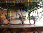
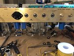
Preamp tube sockets are completely replaced with new sockets and all compromised wiring also replaced as well. The DC heaters are officially done, as is the dual bias circuit.
Next up is to will be to assemble:
2nd master volume
global resonance control
wire the new inputs
Last will be the relay board
I feel like I’m on the downhill slope! I’ve amassed quite the collection of old, worn, or defective parts out of this build. Stay tuned for a picture of the pile ?
Next up is to will be to assemble:
2nd master volume
global resonance control
wire the new inputs
Last will be the relay board
I feel like I’m on the downhill slope! I’ve amassed quite the collection of old, worn, or defective parts out of this build. Stay tuned for a picture of the pile ?