CornNutz
Well-known member
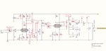
I've almost completed the schematic
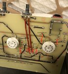
But I'm stumped on r36. Something should be there (a jumper, or resistor) or the amp doesn't appear to work. That's where the junction of the 470k/470k voltage divider feeds signal into the grid of v2a (pin 7)
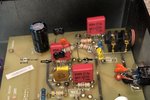
Did you take these photos while you were tinkering with that spot?, or am I missing something?
Thanks!
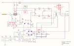
But I'm stumped on r36. Something should be there (a jumper, or resistor) or the amp doesn't appear to work. That's where the junction of the 470k/470k voltage divider feeds signal into the grid of v2a (pin 7)
Did you take these photos while you were tinkering with that spot?, or am I missing something?
Thanks!