1974 120W SL/A Restoration Project v2.0

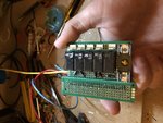
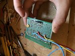
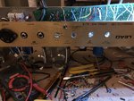
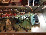
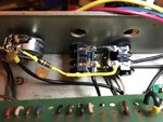
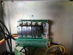
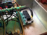
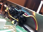
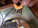
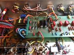
Relay board is half way done. I added the bypass switch for the effects loop, I couldn’t find a SPST switch built into a 1M pot that I liked.

The switch will just control the relay from the back similar to the footswitch control. I go back and forth as to whether I want it to defeat the relay entirely or just control the relay.
 

Attachments

  • 13421DA3-E838-48C9-90E2-6EB68A5C45C2.jpeg
    13421DA3-E838-48C9-90E2-6EB68A5C45C2.jpeg
    103.4 KB · Views: 848
  • 9DF822B5-92FB-4E87-80A6-2C3F631DC1AF.jpeg
    9DF822B5-92FB-4E87-80A6-2C3F631DC1AF.jpeg
    110.3 KB · Views: 852
  • 73DD380A-9D8A-4884-B494-9BB50C2FBCA6.jpeg
    73DD380A-9D8A-4884-B494-9BB50C2FBCA6.jpeg
    116.6 KB · Views: 850
Signal inputs mounted, wired up, and ready for connection to the relay board. Relay board is mounted and wired up to the supply.

Next are the footswitch inputs, then resonance, and last is the second master.

The effects loop can’t be installed or wired up until I have it on and biased with the new tubes to get an accurate new B+ with the removed preamp heaters which will cause the B+ to raise.

Still a lot of work to do, but it’s getting there.
 

Attachments

  • BAD79C0A-1D67-476C-8C7A-44D31543CF1D.jpeg
    BAD79C0A-1D67-476C-8C7A-44D31543CF1D.jpeg
    127.1 KB · Views: 796
  • F75A11DE-02B1-4159-8E4C-8B0FFF3F9804.jpeg
    F75A11DE-02B1-4159-8E4C-8B0FFF3F9804.jpeg
    98.3 KB · Views: 804
  • 4E0B2F49-ED02-4795-9DA0-A23456DE6003.jpeg
    4E0B2F49-ED02-4795-9DA0-A23456DE6003.jpeg
    107.5 KB · Views: 806
I think I’m going with a like new headshell for this one but using the original hardware of my beat up headshell to add some character.

What’s the opinion of stoneage vs sourmash vs mojotone cabs? Who’s the best to go to?
 
I've used all three and they were at different time periods. The Stoneage cabs were super solid but separated at the seams...but this was very early in Stoneage history.

Mojotone are fairly cheapish, quickly thrown together. You can do better.

Sourmash, no complaints. Fast, reasonable, great looking.

My guess is Stoneage and Sourmash are prob comparable regarding quality. The purple headshell in my Superbass build is Sourmash and I have a Hiwatt style cab from them too.
 
I really like the attention to detail on stonage head cabs, the rounded corners and all look great. Price-wise though they're up there at $400 not including shipping or taxes. Sourmash is priced very reasonably at almost half the cost. If they are similar in quality from what you're seeing, whats the extra cost for?
 
Could you install a separate transformer (to power the tube heaters), along with an onboard variac? I suppose a variac wouldn't need to be mounted on the amp though.
 
Goat":qni6flg4 said:
Could you install a separate transformer (to power the tube heaters), along with an onboard variac? I suppose a variac wouldn't need to be mounted on the amp though.

Anything is possible, but a separate transformer for the heaters wouldn’t do much for noise that couldn’t be done with the PT’s original heater tap. You wouldn’t use a variac, you would purchase the secondary transformer with the correct step down ratio to the AC voltage needed. It would add weight, cost, complexity, and not provide much benefit over the stock AC winding beyond possibly removing the stress from the heaters off of it.
 
I built an amp that had the London Power Power Scaling. Part of that is installing a small transformer for the heaters and then using the Scale pot to control voltage (you can also choose to only scale the power tubes and leave the preamp voltage as is, which is what I did). I did not implement it to do the EVH-variac type of thing but it could be used that way.

FWIW, the idea behind the amp above was to scale back power tube voltage and then scale back PI drive to the power tubes via PPIMV so you get "cranked amp tone at low volumes" and the amp was a Trainwreck Express (an amp that is known for being cranked). In practice you could get 99% of all the tone it had to offer by using just the PPIMV. Sold it.
 
glpg80":1d7em73m said:
Goat":1d7em73m said:
Could you install a separate transformer (to power the tube heaters), along with an onboard variac? I suppose a variac wouldn't need to be mounted on the amp though.

Anything is possible, but a separate transformer for the heaters wouldn’t do much for noise that couldn’t be done with the PT’s original heater tap. You wouldn’t use a variac, you would purchase the secondary transformer with the correct step down ratio to the AC voltage needed. It would add weight, cost, complexity, and not provide much benefit over the stock AC winding beyond possibly removing the stress from the heaters off of it.
I had a Mojave "Dirty Boy" amp w/onboard variac. It was cool, but not worth the added weight. Anything below 110VAC started to sound bad, so it was sort-of pointless. Hearing the filter caps discharging/recharging was sort-of cool, but not practial for actual use. Line voltage sweet-spot was 117VAC. You could twirl the biasing as well, but spec'd baising sounded best. I sold it, and never looked back. After about 4-5 weeks, the guy who purchased it begged me to buy it back.
 
Yeah power scaling wise it’s been done before.

Blues Saraceno played a Mojave amp called the dirty boy that had a built in variac. You can see the amp and hear it here. There weren’t many dirty boy amps made from what I remember.

 
Made some more progress last night.

Finished the input jacks and wiring for the relay controls. I also finished one relay mode connection related to the HI/LO switching as well.

I have the footswitch to modify to work with the amplifier, other supporting mods for the amp, and then it should be good to go.

It’s getting there slowly. Very tedious work.
 

Attachments

  • 48A2551D-0DE5-44BB-B296-D7392C608D87.jpeg
    48A2551D-0DE5-44BB-B296-D7392C608D87.jpeg
    108.8 KB · Views: 753
  • 7EE94C60-FD9B-4A28-8ED3-DD96D7B0CED1.jpeg
    7EE94C60-FD9B-4A28-8ED3-DD96D7B0CED1.jpeg
    88.9 KB · Views: 751
No pics as it’s been done a thousand times, but finished integrating a global resonance tonight.

Next to be posted will be integration of the true dual master volumes, one in the rear and volume II in the front as normal.
 
glpg80":k6v4j3df said:
No pics as it’s been done a thousand times, but finished integrating a global resonance tonight.

Next to be posted will be integration of the true dual master volumes, one in the rear and volume II in the front as normal.
It looks great! Are you implementing any switched NFB adjustments? That could be cool. It was one of the nicer features of the old 6100LM.
 
SpiderWars":1cypn3h4 said:
glpg80":1cypn3h4 said:
No pics as it’s been done a thousand times, but finished integrating a global resonance tonight.

Next to be posted will be integration of the true dual master volumes, one in the rear and volume II in the front as normal.
It looks great! Are you implementing any switched NFB adjustments? That could be cool. It was one of the nicer features of the old 6100LM.

Thanks man I really appreciate it!

Your build also helps inspire me to make progress on mine.

Not at the moment. I don’t really follow all of the latest in diode clipping or Jose mods. I do desire to make it more aggressive, but don’t really know how and don’t have the time to fiddle.

I also think a little goes a long way, having a resonance vs not having one will help open the amp up some and give it some depth. This amp was modded in the 80’s from what I can tell and sounded good enough for me as-is when I grabbed it to do this project a year ago. It was easy to play and had the Marshall character.

My gameplan is just to make it reliable and user friendly with features that modern amplifiers need to get played live and not become studio queens.
 
I was saddened to find out a previous owner had broken and resoldered the original treble pot for the amplifier. I was almost done wrapping up the last wire for it and it fell apart as soon as I put heat to it.

The point of this build is reliability and gig friendliness. So I replaced the pot with a new CTS pot that I had on hand. I’m not happy about it as it’s not in the range of the original, but it is what it is.

I also only have to finish the relay connections and the effects loop wiring. Because the effects loop wiring can be done with the board mounted, I mounted the board back down and it looks great!

Getting really close to initial fire up. It will be a while before it’s complete though as I need to buy some socket bias probes, new tubes, another multimeter, and a new oscilloscope for my bench with a built in waveform generator.

I did order some new old stock ceramic capacitors to tune the resonance modification when the time comes.
 

Attachments

  • 758D7A35-1DB6-4103-8781-4271A4537F80.jpeg
    758D7A35-1DB6-4103-8781-4271A4537F80.jpeg
    254.2 KB · Views: 699
  • 93A1BFBA-D03F-45EB-979A-82B31A9D8C53.jpeg
    93A1BFBA-D03F-45EB-979A-82B31A9D8C53.jpeg
    397.4 KB · Views: 701
It is getting really really close and I cannot wait to fire this thing up. The shielded wiring combined with the recap and DC heaters should make it extremely quiet for the amount of gain that it has.

I’m also modifying the V4.1 metroloop. I know it will void the warranty, but I plan to use the included bypass switch as a line level and rack level out switch instead. There’s a switch on the board that needs to be removed to make it happen :)

I also need to order a new filter cap for the metroloop. The included one is too tall as I plan to mount it upside down. The one thing I haven’t figured out is how I’m going to mount it right side up to tune the levels properly before permanently mounting it upside down. V4.1 comes with a potentiometer on board that needs setting.

It’s getting close but there is still an ample amount of work to do. And I need to upgrade my bench to even be able to properly monitor it lol
 
I think Shea (Monomyth) said one way is to somehow temporarily mount it vertically on just one of the jacks and dial it in, then swivel it into position. Something like that.
 
That makes sense actually. I need the new scope to monitor the return level with the loop and with the loop bypassed. You can float a new digital scope but it’s super dangerous to float an analog scope like I currently have. I won’t get into that topic here because that’s a rabbit hole if there ever was one.

I’ll need a C clamp meter for monitoring mains current draw, a meter for B+, a meter for DC supply voltage, and a meter for bias voltage.
 
I have an old Kenwood...those old instruments are pretty cool and mine seems sturdy. But it's not like I do anything very useful with mine. Can you just pull the fuse and measure across the fuseblock instead of using the c-clamp?
 
Back
Top