Resuming my new project - Hilbish GT120

  • Thread starter Thread starter MadAsAHatter
  • Start date Start date
MadAsAHatter

MadAsAHatter

Well-known member
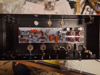
I just received the first parts of a future project. The chassis, faceplate, and PCB come into today. I wasn't expecting it to be delivered until tomorrow so it was a nice surprise to see it a day early. This will be a Hilbish Design GT120 amp build. It's pretty much a straight clone of a 70's Matamp GT120. I intend on it being mainly a bass amp, but like that it can double for guitar if I want some stoner/doom fuzz tones.

Unlike the other amp build project I did, this one isn't a kit. I'll have to source all the parts myself and there are no full instructions. Hilbish supplied only the schematic, wiring layout, BOM, voltage chart, and a handful of build pics. I'm sure any experienced builder could make do with less. Me being pretty much a novice it feels a little intimidating without the crutch of instructions. But the layout doesn't look overly complicated where I couldn't follow it and I also feel it's another small step in my journey.

I'm not starting this right away. I'm planning on doing an Allen Chihuahua kit build first, but couldn't pass up getting the PCB & chassis for nearly half off. I saved enough that it would cover the cost of a Toneclone PT for it. While I'm working on my other projects I'll be getting the parts togther for the GT120 so I have them all in hand for when I start. I'm looking forward to the challenge of this build and having something a good bit different from my other amps.

1703031003227.png
 
I had the pcb from them and never bothered with it. I'm doing a pcb build now that is the same as the hillbish but the guy who did it found a couple issues with the hillbish design (I think they were missing a cap around the nfb section) and corrected it.

At any rate, if you need any help on the iron I have some info for a company that worked on the original transformers and I also have part numbers for a heybooer set that is supposed to put around 500v on the plates. I think the first company ran about 380 shipped from the UK. The heybooer was about 410 minus the choke.
 
I got a long way to go but I'm stuck until I get the transformers.
 

Attachments

  • 20231205_190552.jpg
    20231205_190552.jpg
    3.6 MB · Views: 274
I had the pcb from them and never bothered with it. I'm doing a pcb build now that is the same as the hillbish but the guy who did it found a couple issues with the hillbish design (I think they were missing a cap around the nfb section) and corrected it.

At any rate, if you need any help on the iron I have some info for a company that worked on the original transformers and I also have part numbers for a heybooer set that is supposed to put around 500v on the plates. I think the first company ran about 380 shipped from the UK. The heybooer was about 410 minus the choke.

I'm not overly worried about it being 100% vintage correct or not as long as there are no detrimental flaws in the Hilbish board. I'm assuming since others have built it that's not the case. My big focus is that it works and sounds decently good.

I've only done a quick search for a transformer sets and saw Mercury had some. Outside of that I haven't done much shopping around. I'll probably PM you later on about those Heyboer part numbers after I do a little more looking around.
Yeah no problem. I can send you the info for the UK made ones too.
 
It took me a bit to finally get all the parts together. I'm still waiting on the transformers, but they've been ordered and I have everything else on hand.

I started doing a little bit this morning and got most of the the components on the PCB. I didn't put any of the lead wired (except one) or diodes on yet. I'll save that for later. I didn't realize how big some of those orange capacitors would be when I ordered them. I was concerned they'd be too big and get in the way of other components, but they ended up fitting just fine.

1713545943581.png
 
After a couple project jumped the line and sitting on it this one for over a year, I'm finally getting back to it. I'm determined to see it through before I start any other project.

I got the transformers and some other hardware mounted and put a couple heater wires on the power tube sockets. Also, I'm in the middle of making a plexiglass faceplate that will work better with a headshell I made a while back.

1757958623537.png
 
After a couple project jumped the line and sitting on it this one for over a year, I'm finally getting back to it. I'm determined to see it through before I start any other project.

I got the transformers and some other hardware mounted and put a couple heater wires on the power tube sockets. Also, I'm in the middle of making a plexiglass faceplate that will work better with a headshell I made a while back.

View attachment 416263
That looks vaguely familiar.

Screenshot_20250916_112630_Photos.jpg
Screenshot_20250916_112706_Photos.jpg
Screenshot_20250916_112647_Photos.jpg


Hope it comes out great. It looks like a beast of an amp. I sometimes think I should have went with the EL34 loaded 120 vs the KT88 loaded 150. Don't get me wrong, it sounds amazing, but over the years between different amps I've learned I'm really an EL34 guy. Clean, dirty, or filthy it doesn't matter it's those upper mids, and the way the bass and treble compress just right when you crank them.
 
I'm working on things during my breaks at work so it's been a little slow going. 20 minutes here, 30 minutes there, but I've made a little noticeable progress. I also had to order & wait on a new socket because I accidentally snapped one of the pins off. I have to double check it, but I should have the power tube sockets all wired up. The green heater wires from the PT are huge so I had to step them down to smaller wire so they fit on the pins. It could be a little neater, but everything looks solid.

Next up will probably be wiring the preamp tube sockets. I have a feeling that's going to be "fun". Looking at the diagram V1 has a lot going on with it to fit in that tight space.

1758804091847.png
 
A little bit more work done. The OT, impedance selector and speaker jacks are now wired up. Of course my dumb ass went and wired everything upside down. I'm checking my work and it dawned on me. Wait a damn minute here, sumpthin' ain't right... So I had to pull it all apart and do it over again. After I got it all straightened out I figured that was a good place to stop before I fucked up something else. LOL!

1759416946602.png


1759416911226.png
 
A few extra things done today. Cap cans, power, voltage selector and fuses are wired up. I have a handful of the grounding trimmed and stuck in place, but I haven't soldered any of that yet. Now that most of the transformer wires are hooked up and out the way I feel like I'm making progress.

1759517302528.png


1759517238358.png


1759517255831.png


1759517279411.png
 
So V1 has all kinds of stuff going on with it in a tight ass space. All the normal leads, plus a couple resistors and caps smushed in there and connected to the drive & bass boost knob. All of that was wired as point to point. So instead of trying to cram it all in there I laid it out on a terminal strip to where it would be easier to deal with. I can't take credit for the idea though. I saw a pic of this done by someone else who was building a GT120 clone.

Probably can't see it in the pics, but its bolted to the chassis using one of the V1 screws. It fit nicely, doesn't bump on anything, and I didn't have to drill any extra holes.

PS. this made things easier, but I still hate terminal strips.

1759857645566.png


1759857655615.png
 
Slowly but surely I'm making progress to the point I'm starting to see the finish line. Over the last few days I did the Bass-Boost, Drive, Volume and V1 tube socket. It looks a little bit of a mess, but it's about as neat as I can get it. Even with moving the point to point components to the terminal strip it's still a lot of stuff in a tight space.

Last things to do is V2 tube socket, the rest of the front panel knobs and connect any remaining wires to the PCB.

1762533807373.png
 
One step closer to completion. V2 is wired up and a few little extra things on the front panel pots. I was going to hit the FX send & return jacks too then realized I didn't have any 2 conductor shielded wire on hand. I could probably have done it using 2 pieces of single conductor wire, but then that would just be another wire flopping around. Aside from that, the last of it should be the PCB connections. It looks like a mess of spaghetti noodles right now. It should look cleaner once I start hooking all the wires to the board. Key word... "should" LOL!

The other thing to do is make a new faceplate. This will be the third one I've done for this amp.
My current process is using plexiglass. After getting the sheet cut to size and holes drilled, I use decal paper for labels then spray a background color. My original color scheme was green labels with black background. You couldn't see the labels against the black background on the first one I did. I changed the background color to white. The second plate I made looked perfect. I had it on the amp, then disaster struck. I bumped the faceplate with the soldering iron melting a spot in a nice conspicuous place; followed by some choice words. Third time's a charm I guess.


1763126141509.png
 
I think I'm about done with what I'm going to do on this build. Everything is complete except for running the lead wires to the PCB. I'm going to send it off to Rob DeAntonio (Jaded Faith/EVO Amps) to finish off. I built it in short spurts over the course of almost 2 years. Even though I'm confident I did it all correctly, I want a set of professional eyes on it to make sure I didn't miss anything. Also, when reviewing my work I noticed a couple of inconsistencies between the schematic, layout, and material list. I went with schematic, but again I want a professional set of eyes to look it over. I'd rather pay a little extra to have Rob check it out and clean anything up than switch it on and it go up in smoke.

And I decided not to connect the leads to the PCB to make it easier for Rob to get the PCB out the way. Because everything is a bit tight in there he would likely have to unsolder most of that if he needed to lift it out. I did go through to trim & label all the leads. So hopefully that will make things a little easier for him too.


1763735132369.png
 

Similar threads

MadAsAHatter
Replies
4
Views
436
EyesOfTheSouth!
E
MadAsAHatter
Replies
11
Views
815
NowYou'rePlayingWithPower
MadAsAHatter
Replies
42
Views
3K
Racerxrated
R
Back
Top