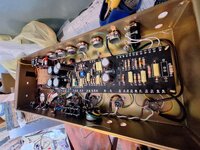
Advice: 1st Amp Build - Mojotone 1978 Brit Style 50w JMP

So according to MojoTone, the 100k NFB resistor is wired to the 8 ohm output tap of the OT. I was actually asking this question recently here. However, I did read on other places, that their NFB resistor was wired to the 4 ohm tap in their JCM800 RI. Maybe that`s a difference as well.

You could try different cap brands as coupling caps. I just finished a TAD Kit, that is basically a Mojotone Kit, and I`m planing to experiment with different caps. While doing so, I will as well pay attention to the "right" foil orientation when installing the caps. Haven`t done this in the first place.
I think the 800 Mojo Kit is on the 16 ohm tap.
 
Here's the two schematics... 800 on top and 50 on bottom
800.png


50.png
 
I actually just finished a 2204 build with the Headfirst st1 board. I usually complete these and they work first power up or shortly thereafter. This one I built with the standard schematic then a buddy gave me some mods to do and it sounds really good now. I'm doing the depth mod and changing one cap value and I didn't have any of the values needed in stock. I thought about doing caps in parallel/series to get the values I needed but I'm doing this for a buddy so I want to have it as clean as I can.
 

Attachments

  • 20231209_124138.jpg
    20231209_124138.jpg
    4 MB · Views: 36
I actually just finished a 2204 build with the Headfirst st1 board. I usually complete these and they work first power up or shortly thereafter. This one I built with the standard schematic then a buddy gave me some mods to do and it sounds really good now. I'm doing the depth mod and changing one cap value and I didn't have any of the values needed in stock. I thought about doing caps in parallel/series to get the values I needed but I'm doing this for a buddy so I want to have it as clean as I can.
That looks so clean Clint.
 
So this is pretty close to final form. I'm adding a depth control where the half power switch would typically be on the back panel. I'm definitely getting better each build. I've learned a lot from V2 amps, Daniel at deaweald audio, Alex from Sirius, Nik, Kyle Rhodes and of course Jason Tong. I'm trying to get out of my comfort zone for these next couple builds.
1000004215.jpg
 
Here's the two schematics... 800 on top and 50 on bottom
View attachment 271653

View attachment 271671
Note that the Presence controls are different and those are part of the NFB voltage divider with respect to AC. But that only exaggerates the difference in NFB between the two. The British 50 is from the 8ohm tap (less signal than 16ohm) and more of it is being bled to ground via the 5k Presence pot (both Presence pots are in parallel with the 4k7 PI ground resistor so it's not as big a difference as it might seem).
 
So this is pretty close to final form. I'm adding a depth control where the half power switch would typically be on the back panel. I'm definitely getting better each build. I've learned a lot from V2 amps, Daniel at deaweald audio, Alex from Sirius, Nik, Kyle Rhodes and of course Jason Tong. I'm trying to get out of my comfort zone for these next couple builds.
View attachment 272037
Looks great! Are those 5v rectifier leads exposed?
 
For the experienced out there... I've got the hardware mounted and am about to start wiring it. I'm planning on wiring it identical to Mojotone's wiring diagram below. Should I wire it differently? I've heard there is a better way to ground it but I don't know what that would be? I'm thinking it might be best to wire it like the diagram and then fix the grounding later so I can understand the difference.
1703792045237.png
 
I like shielded wire on both grids of v1 and the 68k connected to the tube socket not the input jack. I don’t like the optional cap on v1 but that’s easy to remove. I also like to heat shrink the 470k/470p cap from the low jack to the gain pot as it can get a bit noisy.
 
I like shielded wire on both grids of v1 and the 68k connected to the tube socket not the input jack. I don’t like the optional cap on v1 but that’s easy to remove. I also like to heat shrink the 470k/470p cap from the low jack to the gain pot as it can get a bit noisy.
What difference does the 68k on the tube socket make? I noticed this is how it is on the 800 diagram.
 
It benefits noise and stability. Not apparent for stock amps albeit still recommended, but it’s absolutely critical as you begin to pile on the mods and gain.
I agree. I recommend looking at the Valvestorm site and check out the instructions for the metro 50 watt 2204. You definitely don't have to do it identical to this particular layout or the Metro one but there is a lot of good info in those instructions.

Also check out Jason Tong's vids on the Headfirst YouTube page. I learn something new at times when I don't expect it. I still have a long way to go before I can say I'm competent at building but it's nice to see the stuff I'm retaining when looking at other amps.
 
I basically connect the 68k to the tube socket then heat shrink it and the wire connected to it. I've built like 10 amps so far and the part I always screw up on is the input jacks. I don't know why I have a mental block there.
 
I basically connect the 68k to the tube socket then heat shrink it and the wire connected to it. I've built like 10 amps so far and the part I always screw up on is the input jacks. I don't know why I have a mental block there.
It does look tricky.. especially on the weird way they diagramed it on the pic I posted above. I also have the instructions from the old StewMac 800 that was made by Mojotone and they have diagramed it better so I'm hoping I don't screw it up.
 
Good discussion in this thread guys. Thanks for all of the tips. I've started the same Mojotone Brit 50 kit. I really like the way the Stewmac guide is written and how it walks you through every step. You can find it here.

I have a two questions right now:

1) The Aiken Amps website has a page on grounding here. He mentions a "star" ground system being ideal, which helps minimize the heavy ground currents from the power supply and output stage interfering with the input gain stages. You do this by grouping most of the ground wires together and then connecting them to the chassis at a single point (or a few points).

If you take a look at the below Stewmac Brit 50W diagram, you can see they follow this idea:

Stewmac_Brit_50.png

Compare this to the Mojotone diagram below. There is less grouping of grounding going on. Each filter capacitor and power tube has it's own ground lug.

Mojotone_Brit_50W.png

Will the noise floor be significantly increased by using the Mojotone grounding scheme instead of Stewmac's? Or is the difference negligible?

2) Is there any benefit to using the transformer legs + chassis connections as the grounding points vs just chassis alone?
 
Last edited:
Electrons are actually sourced through the chassis (electron flow is opposite of conventional current flow). The star grounding eliminates the chassis from having any significant impact to you noise floor by sourcing electrons from a single location.

I did not go through with star grounding in my prototype but did my best to eliminate the number of different ground references. The more you can make the bottom layout look like the top layout in terms of grounding the better off you are for reducing your noise floor assuming your component choices aren’t noisy. In a few locations I use noisy components for their sound so insane ground point elimination efforts wouldn’t give further audible results anyway. Noise in an amplifier is a sum of many topics all together at once including layout which you could also change but is way more advanced.
 
Last edited:
Back
Top