glpg80":2ymzm2rm said:
It doesn't help the schematic doesn't match the layout.
Regardless, I think I reverse engineered it assuming they use a DPDT. It's quite cunning actually. They take what looks to be a negative feedback circuit but is actually a bypass forward path when the pedal is "off" which is still technically in circuit due to the first buffer.
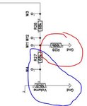
Here's a fix you can try - unsolder W3, but leave it connected to the DPDT. Solder the open end of that wire to the tip/hot of the input jack which also goes to W2. The W3 hole should be open. See if that does what you want for true bypass.
There shouldn't be a volume drop associated with when the pedal is off and on. If there is a volume imbalance doing this, then shoot me a PM. I have something else to recommend which is similar but uses a bit of their own passive circuitry to balance the off/on states.
And fuck Ceriatone for their error-prone mesa style schematics. This is 2018 not 1978. They literally have the single-sided board design captured in the same document.
As for the schematics and single sided board, they are accurate and true to the original Klon from what I can tell. A little blurry in the document, but in typical Ceriatone style they don't ever design anything just copy it. The market here is for people who want a Klon replica.
As for the recommended mod, your signal will be heavily loaded down. Not ony is the R28 - 100K resistor to ground that is still in circuit, but also a maximum of 78K (R27 - 68k & volume 10k) paralleling that to ground (depending on volume setting). Your signal will we seeing no more than 44k to ground and loose alot of volume and high end. Also when the effect is on, you clean signal would still be in signal only attenuated by a 68 resistor. The foot switch only shorts out either of the 68K resistor is really more there to prevent popping on one side and shunts either the LED of the effect signal to ground with the other half.
These pedal are going for $300 or so, and there are alot of cheap copies out there that are true bypass. I'd leave it alone, get a looper, or pick up a cheap knock-off like the Caline that is true bypass.