Anyone want to help me fixing/modding my JCM800? Clip Added!

  • Thread starter Thread starter JakeAC5253
  • Start date Start date
JakeAC5253

JakeAC5253

New member
I'm considering modding my JCM800 2203, and I'm going to do all of the work myself, so please no recommendations for places to take the amp, just not interested at this time. So I have this schematic of a 2203, and this is the assumption that I have for what is going on inside, though I know there were a lot of changes made to the amps, to the extent that the model names on the faceplate were mere suggestions as to what was going on inside a Marshall. If anybody has a more accurate (or more legible!) schematic than this one, I would appreciate it.

JCM800 2203 Pre: (scroll down, the first schematic is a plexi style)
http://www.drtube.com/schematics/marshall/jcm800pr.gif
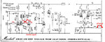
JCM800 2203 Power:
http://www.drtube.com/schematics/marshall/1959pwrm.gif

Here are some pictures of the actual amp for reference:
https://dl.dropboxusercontent.com/u/883 ... 154459.jpg
https://dl.dropboxusercontent.com/u/883 ... 151854.jpg
https://dl.dropboxusercontent.com/u/883 ... 151901.jpg

I hope to mod the amp for probably the same reasons anyone would. More gain range and tame the needles. According to memory, I believe that one thing to do to increase gain is to make the Plate resistors on the gain stages into 220k, and the Cathode resistors into 1k (possibly 820ohm) bypassed using capacitors that filter below 80Hz. What to do about the needles? I'm fine with the amount of bass the amp currently has more or less, so I don't want to mask the problem by adding more lows, I'd rather target the highs. Filter caps across the plate resistors? I think I've seen Mesa use that technique in the Recto style amp. What are people doing to reduce the needles without greatly changing the amp? Any other well-recommended mods I should look into?
 
Keep the anodes in the first step.
V1B cathode to 2k7 & parallel with a 680nF, take out the gainpot cap and install a fixed depth a la Friedman, which is a 220k with a 4n7 parallel between the NFB resistor R 24 and the imp switch. Probably a 500k log gain pot. Thats hotrodded and meaty.
Sweet spot in this design gainwise is the cathode of V1B.
 
If you want to mod it just for the experience of modding it (like I did) go for it. BUT after my journey of modding and actually building one from scratch, the only mod I kept was the effects loop. Nowadays, the mods I do are pedals in front of the amp. In fact, I went thru a LOT of pedals and configurations including the TS, OCD etc. in front of the high gain input as well as the Bogner Ecstasy Red and Blue in front of the low gain inputs. I ended up with a stock 2204 (except for the fx loop) with a Boss GE-7 in front of it for lead boost. I've got a couple of delays, pitch shifters and a boost pedal in the loop and I'm pretty happy.
 
duesentrieb":18zswmqt said:
Keep the anodes in the first step.
V1B cathode to 2k7 & parallel with a 680nF, take out the gainpot cap and install a fixed depth a la Friedman, which is a 220k with a 4n7 parallel between the NFB resistor R 24 and the imp switch. Probably a 500k log gain pot. Thats hotrodded and meaty.
Sweet spot in this design gainwise is the cathode of V1B.

Awesome, thanks for the ideas. So would that look like this then?

https://dl.dropboxusercontent.com/u/883 ... %20Mod.png

If so, I like it. Looks like the lower impedance after the input stage should be a nice natural way of softening the highs without changing the way the amp sounds too much, and deleting the bright cap would be cool too, don't have to have the gain on full to get a full sounding tone. It looks like according to the schematic the V1B already has the values you recommend. Will this add any gain, or just give a fuller sound?
 
Just Mike":2i5p586s said:
If you want to mod it just for the experience of modding it (like I did) go for it. BUT after my journey of modding and actually building one from scratch, the only mod I kept was the effects loop. Nowadays, the mods I do are pedals in front of the amp. In fact, I went thru a LOT of pedals and configurations including the TS, OCD etc. in front of the high gain input as well as the Bogner Ecstasy Red and Blue in front of the low gain inputs. I ended up with a stock 2204 (except for the fx loop) with a Boss GE-7 in front of it for lead boost. I've got a couple of delays, pitch shifters and a boost pedal in the loop and I'm pretty happy.

I'm actually big on switchable mods. I always make my mods switchable from the front panel so I can have stock at one position on the switch and mod on the other position. I did my 5150 this way, and I have no regrets, both positions sound great. I did the same thing you are describing with overdrive pedals, just about lost my mind in the process lol... just.. one.. more.. mod. and it'll.. be.. perfect. I don't plan on going that crazy with it again. Although I did do some cool things with the Big Muff circuit that I'd like to revisit sometime, because they all exploded from over-modification.
 
If that amp is stock don't mod it. It's a 1981 first year JCM just my opinion.
 
agree, just build another JCM800 clone and mod that. The funny thing is that you can start adding mods to this iconic
amp and it changes the sound radically away from the marshall vibe, hence build it independently.

Sometimes you can just do things to this amp to improve it like add a 100k resister to the MV wiper and that resolves some
of the JCM800 issues. Clip out the treble cap. Tweaking the tone shaping early on to get better distortion of specific frequencies, small
changes.
 
Marshall Law":ha0kpq2q said:
If that amp is stock don't mod it. It's a 1981 first year JCM just my opinion.

mdc1mdc11":ha0kpq2q said:
agree, just build another JCM800 clone and mod that. The funny thing is that you can start adding mods to this iconic
amp and it changes the sound radically away from the marshall vibe, hence build it independently.

Sometimes you can just do things to this amp to improve it like add a 100k resister to the MV wiper and that resolves some
of the JCM800 issues. Clip out the treble cap. Tweaking the tone shaping early on to get better distortion of specific frequencies, small
changes.

The amp came to me modded by the previous owner. I gave it to a local amp tech and told him to mod it back to stock spec, but I don't really trust his work because he didn't even bias the power tubes, gave it back to me biased at 8mA. I had to fix that shit myself, so I probably have to go over the entire circuit to ensure that it's actually stock, which is what I paid him to do in the first place. Either way, I do plan on having any mods be switchable, because it's very important to me to have a completely stock amp on at least one switch position. The faceplate is already drilled from the previous owner, so I may as well put a 4PDT switch there and get some extra juice out of it. Currently, the amp doesn't sound as good as my 5150 in person or on tape, so it's either got a fucked up circuit that needs to be rectified, or some mods would make it sound better.
 
Add a depth pot. 1 meg audio taper push pull with a .001 ceramic cap across it and another .002 across the switch (so when pulled it will be .003). Of course you can try any value, but what I listed is the sweet spot IMO.
 
psychodave":3ep2u4hw said:
Add a depth pot. 1 meg audio taper push pull with a .001 ceramic cap across it and another .002 across the switch (so when pulled it will be .003). Of course you can try any value, but what I listed is the sweet spot IMO.

Dave! How you doing man? Long time no see, I just came back myself.
 
I reckon the only mods old 2203's need is a Metroamp effects loop and an old SD-1 run into them :)
 
JakeAC5253":2luss6xn said:
You forgot to draw the changes to the 10k cathode. Will draw you something later.

here . . .

also replace the 68k on the shielded input cable to 1k or something with a low value (less hiss when idle).
also replace the wire between treble (mid) and the master vol with a 470k resistor to get better control for the whole tone stack.

Do all that step by step and start to replace the 10k of V1B. You may experiment here with 4k7 (or add a 10k in parallel to result 5k) and then continue.
Also you can follow Dave's suggestion with an adjustable depth or - if you don't want to drill - use the fixed version I've drawn.

Olaf
 

Attachments

  • 800mod.jpg
    800mod.jpg
    246.3 KB · Views: 4,420
I'm so glad I am looking into this again, I am finding things I either didn't know, or completely forgot about. The power tubes won't bias higher than 25mA. The previous owner had it modded to use KT77s (or 88s, I don't remember) and a PPIMV, and I guess the tech I took it to didn't bother changing the bias range resistor. Another thing I'll have to do my damn self. I'm not sure if the PPIMV was removed entirely or if the current master volume is stock. Also, apparently the bright cap on the gain pot was already cut, so that's notable. Jeez, I wonder what else in this amp isn't stock. Gee it would have been nice if the guy I told to "mod it back to stock spec" would have actually done the job I paid him to do. Guess its between this forum and myself to get this old girl in shape again. I'll upload some pictures. If anybody has any advice to give or wants pictures of particular things, let me know please.

https://dl.dropboxusercontent.com/u/883 ... 172619.jpg
https://dl.dropboxusercontent.com/u/883 ... 153740.jpg
https://dl.dropboxusercontent.com/u/883 ... 154035.jpg
https://dl.dropboxusercontent.com/u/883 ... 153857.jpg

First priority: Get the circuit back to stock spec and operating at 100% again
Second priority: Modify circuit if necessary, attached to a Stock/Mod switch whenever possible.
 
Master Volume wiring is ok.

If the 1nF over the gainpot is already cut, then you can also cut the 470pF over the 470k resistor which connects the jacks and the gainpot.

For the bias resistor: that was changed and put back to specs for 6550 AFAIK. (27k). You need to try to find the correct value anyway. Should be in a range between 10k and 33k (board indicates 27k). I'd try 15k.
 
duesentrieb":2mkazp7c said:
Master Volume wiring is ok.

If the 1nF over the gainpot is already cut, then you can also cut the 470pF over the 470k resistor which connects the jacks and the gainpot.

For the bias resistor: that was changed and put back to specs for 6550 AFAIK. (27k). You need to try to find the correct value anyway. Should be in a range between 10k and 33k (board indicates 27k). I'd try 15k.

Thanks for looking it over. Interesting, I thought the 47k right above the bias trim was the resistor in question, and I was about to replace that with a 27k. Since the resistor is already at 27k, before I go and replace that with a lower value, is there anything else that could possibly be dragging down the bias current? Possibly worn caps or the transformer itself? The large 50uF filter caps were replaced, but the two small 10uF caps I do not believe were replaced.
 
JakeAC5253":1sqitxz2 said:
duesentrieb":1sqitxz2 said:
Master Volume wiring is ok.

If the 1nF over the gainpot is already cut, then you can also cut the 470pF over the 470k resistor which connects the jacks and the gainpot.

For the bias resistor: that was changed and put back to specs for 6550 AFAIK. (27k). You need to try to find the correct value anyway. Should be in a range between 10k and 33k (board indicates 27k). I'd try 15k.

Thanks for looking it over. Interesting, I thought the 47k right above the bias trim was the resistor in question, and I was about to replace that with a 27k. Since the resistor is already at 27k, before I go and replace that with a lower value, is there anything else that could possibly be dragging down the bias current? Possibly worn caps or the transformer itself? The large 50uF filter caps were replaced, but the two small 10uF caps I do not believe were replaced.
There is a 27k resistor (the carbon comp one) in series with the bias diode. That resistor kind of sets the available supply voltage (from the PT) for the bias supply to work with. There is also a 47k resistor in series with the bias pot. Both of these resistors change when going from 6550 to EL34. That 47k resistor is 56k with EL34s which will raise the bias voltage (i.e. make it more negative).
 
duesentrieb":132i61ya said:
http://www.drtube.com/schematics/marshall/2203u.gif

Of course you can solder another 47k over/parallel to that 47k to increase the idle current.
Thats normal, it is more a question of the tubes than of anything being crapped inside the amp.

SpiderWars":132i61ya said:
JakeAC5253":132i61ya said:
duesentrieb":132i61ya said:
Master Volume wiring is ok.

If the 1nF over the gainpot is already cut, then you can also cut the 470pF over the 470k resistor which connects the jacks and the gainpot.

For the bias resistor: that was changed and put back to specs for 6550 AFAIK. (27k). You need to try to find the correct value anyway. Should be in a range between 10k and 33k (board indicates 27k). I'd try 15k.

Thanks for looking it over. Interesting, I thought the 47k right above the bias trim was the resistor in question, and I was about to replace that with a 27k. Since the resistor is already at 27k, before I go and replace that with a lower value, is there anything else that could possibly be dragging down the bias current? Possibly worn caps or the transformer itself? The large 50uF filter caps were replaced, but the two small 10uF caps I do not believe were replaced.
There is a 27k resistor (the carbon comp one) in series with the bias diode. That resistor kind of sets the available supply voltage (from the PT) for the bias supply to work with. There is also a 47k resistor in series with the bias pot. Both of these resistors change when going from 6550 to EL34. That 47k resistor is 56k with EL34s which will raise the bias voltage (i.e. make it more negative).

Thanks for the advice both of you. I'm trying to understand biasing, but it's apparently more complex than I originally thought. So the 27k determines the max amount of current available for the network made up of the 47k + 22k trimpot to work with. So since my current setup of 47k + 22k seems like it's more or less what it should be (56k + 22k), and doesn't have enough current capability. The best thing to do would be to drop the value of the 27k to get more current potential. Now since I am doing that, should I bother making the 47k into a 56k, or does it not matter so long as the bias reaches what it should?

Just because I don't think I've mentioned these yet.
Power Tubes: 4xWinged C EL34
Plate Voltage: 425V
Target Bias Current: 41mA
 
You can decrease the 27k to get more bias voltage (not current, * - see below) as long as it doesn't go over the bias cap voltage rating (the bias filter caps are probably rated in 150v-160v range). If you can get there that way then leaving the 47k is fine.

As you increase your idle current the plate voltage will decrease a little bit. So you have to keep re-measuring your plate voltage, re-doing the calculation, and adjusting again to get it dialed in. Also, consider that 70% max dissipation as a max and don't just blindly set it there. Listen to the amp at 70% then 50%, see if you like one better and go from there. Run it as cool as you can and still get the tone you like. You may like 55% or 60% better than 70%.

* - just to clarify: you are setting a bias voltage (at the grid) such that it controls the idle current through the tube (from plate to cathode). Under normal conditions, no real current flows in the bias circuit itself, the current is flowing from plate to cathode and the grid (bias) voltage just controls that current.
 
Back
Top