Ceriatone Chupacabra component change questions

  • Thread starter Thread starter ledvedder
  • Start date Start date
ledvedder

ledvedder

Well-known member
Hi everyone! I've been diving back into testing different values with my Chupacabra and I have some questions.

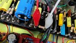
When testing different values of slope resistor, what should I be hearing? Or maybe I'm just deaf ?. The stock value is 47K. I've been piggybacking different resistors across it to give me values of both 33K and 39K, but I'm not hearing any differences.

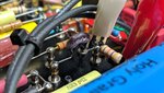
Also, I've been testing combinations of different zeners and diodes. I connect them from the middle lug of the master to ground and set the era switch in the middle. I do get saturation, as expected. But am I hearing only the components I'm connecting, or am I hearing a combination of them, along with the zeners that are already connected (20v and 9.5v)?
 
Diodes go from lug 3 to ground on the master, not the wiper. With the Era switch in the middle the stock diodes are bypassed so you'll hear whatever you've clipped in temporarily.

Slope resistor changes the center frequency of the tone stack. It's easier to hear the difference if you use a pot instead of a resistor, that way you can sweep the pot as you play to really hear the difference it makes. But as you go lower in value, the amp will become less scooped. 47K is more scooped than 33K. The difference should be immediately noticeable...

I personally prefer 33K slope and 18v zeners on one side of the switch and either MPSA06 or 2N5401 on the other.

But if you really want to wake the amp up, go with 33K slope, raise the value of the NFB resistor, lower the depth cap to 2200pF. But lots of other things you can do to turn an already good amp into a monster.
 
FourT6and2":2q6ml2rn said:
Diodes go from lug 3 to ground on the master, not the wiper. With the Era switch in the middle the stock diodes are bypassed so you'll hear whatever you've clipped in temporarily.

Slope resistor changes the center frequency of the tone stack. It's easier to hear the difference if you use a pot instead of a resistor, that way you can sweep the pot as you play to really hear the difference it makes. But as you go lower in value, the amp will become less scooped. 47K is more scooped than 33K. The difference should be immediately noticeable...

I personally prefer 33K slope and 18v zeners on one side of the switch and either MPSA06 or 2N5401 on the other.

But if you really want to wake the amp up, go with 33K slope, raise the value of the NFB resistor, lower the depth cap to 2200pF. But lots of other things you can do to turn an already good amp into a monster.

Would a standard 250K or 500K pot work?

What value do you suggest for the NFB resistor? And what's the stock value?
 
ledvedder":1898a773 said:
FourT6and2":1898a773 said:
Diodes go from lug 3 to ground on the master, not the wiper. With the Era switch in the middle the stock diodes are bypassed so you'll hear whatever you've clipped in temporarily.

Slope resistor changes the center frequency of the tone stack. It's easier to hear the difference if you use a pot instead of a resistor, that way you can sweep the pot as you play to really hear the difference it makes. But as you go lower in value, the amp will become less scooped. 47K is more scooped than 33K. The difference should be immediately noticeable...

I personally prefer 33K slope and 18v zeners on one side of the switch and either MPSA06 or 2N5401 on the other.

But if you really want to wake the amp up, go with 33K slope, raise the value of the NFB resistor, lower the depth cap to 2200pF. But lots of other things you can do to turn an already good amp into a monster.

Would a standard 250K or 500K pot work?

What value do you suggest for the NFB resistor? And what's the stock value?

Any value pot will work. You just need a useable range of like 33K to 56K. If you're clipping in a pot in parallel with the stock resistor, then yeah either 250K or 500K should work. Once you find a position on the pot you like, remove it and measure it's resistance. Then calculate the total resistance in parallel with the stock resistor and solder in a single resistor that gets you close. So if you like the pot set to 120K, that' equals 33.7K when in parallel with the stock 47K. So then use a 33K final resistor.

I think stock NFB is 39K? Take a look at your amp. Maybe try 47K. But once you start down this road, you might want to look into some other changes in the preamp. It's game of balance. You change one thing here, you gotta change another there to compensate and all the things work together.

I could tell you exactly what to change in the circuit but that would ruin the fun for you :D
 
FourT6and2":3fr56vzc said:
ledvedder":3fr56vzc said:
FourT6and2":3fr56vzc said:
Diodes go from lug 3 to ground on the master, not the wiper. With the Era switch in the middle the stock diodes are bypassed so you'll hear whatever you've clipped in temporarily.

Slope resistor changes the center frequency of the tone stack. It's easier to hear the difference if you use a pot instead of a resistor, that way you can sweep the pot as you play to really hear the difference it makes. But as you go lower in value, the amp will become less scooped. 47K is more scooped than 33K. The difference should be immediately noticeable...

I personally prefer 33K slope and 18v zeners on one side of the switch and either MPSA06 or 2N5401 on the other.

But if you really want to wake the amp up, go with 33K slope, raise the value of the NFB resistor, lower the depth cap to 2200pF. But lots of other things you can do to turn an already good amp into a monster.

Would a standard 250K or 500K pot work?

What value do you suggest for the NFB resistor? And what's the stock value?

Any value pot will work. You just need a useable range of like 33K to 56K. If you're clipping in a pot in parallel with the stock resistor, then yeah either 250K or 500K should work. Once you find a position on the pot you like, remove it and measure it's resistance. Then calculate the total resistance in parallel with the stock resistor and solder in a single resistor that gets you close. So if you like the pot set to 120K, that' equals 33.7K when in parallel with the stock 47K. So then use a 33K final resistor.

I think stock NFB is 39K? Take a look at your amp. Maybe try 47K. But once you start down this road, you might want to look into some other changes in the preamp. It's game of balance. You change one thing here, you gotta change another there to compensate and all the things work together.

I could tell you exactly what to change in the circuit but that would ruin the fun for you :D
I don't know, maybe my ears just aren't as tuned as yours? I clipped a 250k pot in parallel across the 47K slope resistor. Actually, the highest that the pot would read is 191K. So that would've equaled about 39K. I was hearing no difference. That is, until I rolled the pot down. At that point the pot was reading around 3K, which equaled about 2.8K. Maybe it has to do with how I have the amp dialed in? My favorite setting is as follows -

80s mode
Gain 1 at 7 pulled out, center toggle
Gain 2 at 4, left toggle
Treble 6
Mids 7
Bass 3
Presence 4
Resonance 2
 
ledvedder":3m35v9md said:
I don't know, maybe my ears just aren't as tuned as yours? I clipped a 250k pot in parallel across the 47K slope resistor. Actually, the highest that the pot would read is 191K. So that would've equaled about 39K. I was hearing no difference. That is, until I rolled the pot down. At that point the pot was reading around 3K, which equaled about 2.8K.

Try removing the stock slope resistor from the circuit and replace with a 33K resistor in series with a 25K linear pot.
Might be easier for you. But yes, the difference between 33K, 39K, and 47K should be night and day...

Make sure you're using a linear pot, not log.

Maybe it has to do with how I have the amp dialed in? My favorite setting is as follows -

80s mode
Gain 1 at 7 pulled out, center toggle
Gain 2 at 4, left toggle
Treble 6
Mids 7
Bass 3
Presence 4
Resonance 2

Those settings seem fine. If you're not hearing a difference with the slope resistor, then something's gotta be wrong. Are you sure you've got it all wired up properly?

How are you wiring the pot?
 
Here's how I'm wiring it.


Attachments

  • IMG_20181230_214931.jpg
    IMG_20181230_214931.jpg
    224.3 KB · Views: 620
  • IMG_20181230_214945__01_2.jpg
    IMG_20181230_214945__01_2.jpg
    70.5 KB · Views: 572
Try a linear pot. That log pot should work though, just most of the taper is bunched up into the last 1/4 rotation. So if you're turning it from like 2:00 to zero, you won't hear much of a difference.
 
Also what's up with the missing 10K dropping resistor on the PI filter cap? I see a lead sticking out under the cap. But there should be one between the sections...
 
FourT6and2":2ywzin3g said:
Also what's up with the missing 10K dropping resistor on the PI filter cap? I see a lead sticking out under the cap. But there should be one between the sections...
Are you talking about this brownish one?
 

Attachments

  • IMG_20181230_223407.jpg
    IMG_20181230_223407.jpg
    176.2 KB · Views: 555
Nope.

The preamp filter cap is the large blue 50+50, 500v thing that says Holy Grail on it. There should be a 10K, 2W metal oxide resistor between the positive poles. In your first photo, it's missing. And there is a bit of a lead sticking out from under the cap on one side. There's also a bit of a red material on the other side I can kinda see. I'm guessing someone modified the filtering for some reason. Did you buy your amp directly from Ceriatone or used? because someone's been messing with it, unless that aftermarket FX loop has something to do with it?

Look at the layout: http://www.ceriatone.com/ceriatone/wp-c ... t-2015.jpg
 
AHA!

I figured it out. This is your amp in these videos. Same name on the blue sticker. Same red material stuck to the cap.
I can see in video two, that the dropping resistor has been installed hiding under the filter cap for some odd reason.

https://www.youtube.com/watch?v=oNYvSF5qPjQ
https://www.youtube.com/watch?v=Ew8cqOkVeLE
https://www.youtube.com/watch?v=3OI3LTxPqoo

Anyway... that's nothing to worry about. As far as the slope resistor goes, yes it should be night and day obvious going from 47K to 33K. Good luck. :)
 
When testing parts, I’ve found it’s always better to lightly solder them in vs using alligator clips. Using clips doesn’t always make the best contact.
 
One of my favorite mods and easy to install on a Marshall type amp, is to add a switch that bypasses the tone stack, with a 250k pot to blend it back in. My modded Marshalls have this and it makes the amp sound massive and raw. It also gives the amps a better feel as well. Killer mod to do :thumbsup:
 
psychodave":6s0goe93 said:
When testing parts, I’ve found it’s always better to lightly solder them in vs using alligator clips. Using clips doesn’t always make the best contact.

The problem is he's using a log pot instead of linear. So he's probably turning it and not hearing a difference because the pot's entire range is bunched up into a 1/4 turn. That, and it's only giving him a usable range of 33K - 39K. OP, you'll get a better idea if you just remove the stock slope resistor and clip in a 50K LINEAR pot instead.
 
FourT6and2":3atv06ra said:
psychodave":3atv06ra said:
When testing parts, I’ve found it’s always better to lightly solder them in vs using alligator clips. Using clips doesn’t always make the best contact.

The problem is he's using a log pot instead of linear. So he's probably turning it and not hearing a difference because the pot's entire range is bunched up into a 1/4 turn. That, and it's only giving him a usable range of 33K - 39K. OP, you'll get a better idea if you just remove the stock slope resistor and clip in a 50K LINEAR pot instead.
What's the easiest way to remove the stock slope resistor? Each side has a large ball of solder. Is it best to just heat up the ball of solder and remove the legs?
 
ledvedder":1l051vnm said:
FourT6and2":1l051vnm said:
psychodave":1l051vnm said:
When testing parts, I’ve found it’s always better to lightly solder them in vs using alligator clips. Using clips doesn’t always make the best contact.

The problem is he's using a log pot instead of linear. So he's probably turning it and not hearing a difference because the pot's entire range is bunched up into a 1/4 turn. That, and it's only giving him a usable range of 33K - 39K. OP, you'll get a better idea if you just remove the stock slope resistor and clip in a 50K LINEAR pot instead.
What's the easiest way to remove the stock slope resistor? Each side has a large ball of solder. Is it best to just heat up the ball of solder and remove the legs?

Solder sucker. Or you can just cut the resistor out if you don't want to save it. But to solder a new one in, you're gonna have to use a solder sucker anyway to clean up the turrets.
https://www.tubedepot.com/products/anti ... ering-pump

Gotta watch how much heat your use. Make sure you don't melt the center conductor insulation on the coax cable going from tone stack to master volume. Otherwise you'll cause a short.
 
FourT6and2":1nuktmel said:
ledvedder":1nuktmel said:
FourT6and2":1nuktmel said:
psychodave":1nuktmel said:
When testing parts, I’ve found it’s always better to lightly solder them in vs using alligator clips. Using clips doesn’t always make the best contact.

The problem is he's using a log pot instead of linear. So he's probably turning it and not hearing a difference because the pot's entire range is bunched up into a 1/4 turn. That, and it's only giving him a usable range of 33K - 39K. OP, you'll get a better idea if you just remove the stock slope resistor and clip in a 50K LINEAR pot instead.
What's the easiest way to remove the stock slope resistor? Each side has a large ball of solder. Is it best to just heat up the ball of solder and remove the legs?

Solder sucker. Or you can just cut the resistor out if you don't want to save it. But to solder a new one in, you're gonna have to use a solder sucker anyway to clean up the turrets.
https://www.tubedepot.com/products/anti ... ering-pump
OK thanks. I have one of those, just haven't had much luck with it. I suppose I'll give it another shot. I just ordered a 50K linear pot. https://www.tubesandmore.com/products/p ... 38-bushing
 
A trick to use with the solder sucker is to melt one side of the tip with an iron. This way you can place the sucker on top of the joint with the iron still touching the part. This way the joint is still hot while sucking. haha
 
The chnage in slipe won't be drastic. What are you trying to change about the tone. Probably better places to tweak.
 
Back
Top