X
Xavier180
New member
Hi Guys! My very first post here ")
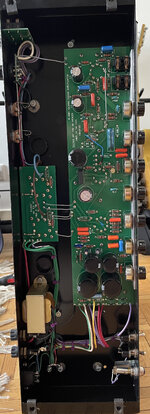
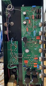
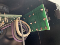
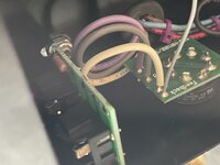
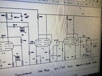
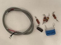
Recently acquired a soldano avenger 50 w/ effet loop. The loop had been disconnected by a previous owner and even though I have in hand the spare components which have been removed I do not know where to put them back to put the loop back in service.
So I am looking for guts photos (to compare with mine) and/or schematic if anyone have them. If it is easy I would do it myself otherwise I'd bring it to a tech but I guess he will at least need the schematics
thanks a lot!
PS: I found on the forum a post by MikeytheG with one photo when he sold his avenger but the angle the photo was taken from, it does not help much