BesaMoogie
Well-known member
Hi,
I recently was able to get my hands on a 6505+ and I already love the amp, although I was actually searching for an 6505. So I was thinking of modding the lead channel of the 6505+ to 6505 specs as the circuit only differs at two positions. I would prefer to have the mod switchable with a push pull DPDT pot to go back and forth.
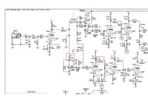
The two differences are basically two caps to get from 6505+ to 6505
C17 = 470pf ---> 2.2nF with 470K in parallel
C2 = 0.001uF ----> 0.022uF
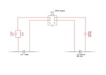
I was thinking of just hocking up in parallel:
1. a 1.7nF and 470K cap/res to C17 and
2. a 0.022uF a cap to C2
That way I should approx. get the desired values of the 6505 circuit (see picture of the mod).
But there`s one thing that boggles my mind. In the schematics, the C2 cap is a 630 volt cap. So the question is, if a DPDT push pull pot can handle the voltage when an additional cap is hocked up in parallel to C2 or not???
I was searching for the specs of push pull pots but was not able to find anything. Probably because those switches are usually used in guitars where low voltage is present.
Most DPDT toggle switches are usually rated at 250VAC and 3A, but then again, we are talking about VDC, not VAC here. I attached pics of the of the schematic and how I was thinking to do the mod. Maybe someone can help me out here?
Thanks!
I recently was able to get my hands on a 6505+ and I already love the amp, although I was actually searching for an 6505. So I was thinking of modding the lead channel of the 6505+ to 6505 specs as the circuit only differs at two positions. I would prefer to have the mod switchable with a push pull DPDT pot to go back and forth.
The two differences are basically two caps to get from 6505+ to 6505
C17 = 470pf ---> 2.2nF with 470K in parallel
C2 = 0.001uF ----> 0.022uF
I was thinking of just hocking up in parallel:
1. a 1.7nF and 470K cap/res to C17 and
2. a 0.022uF a cap to C2
That way I should approx. get the desired values of the 6505 circuit (see picture of the mod).
But there`s one thing that boggles my mind. In the schematics, the C2 cap is a 630 volt cap. So the question is, if a DPDT push pull pot can handle the voltage when an additional cap is hocked up in parallel to C2 or not???
I was searching for the specs of push pull pots but was not able to find anything. Probably because those switches are usually used in guitars where low voltage is present.
Most DPDT toggle switches are usually rated at 250VAC and 3A, but then again, we are talking about VDC, not VAC here. I attached pics of the of the schematic and how I was thinking to do the mod. Maybe someone can help me out here?
Thanks!