C
ClintN667
Well-known member
Hey guys. Im doing one of Burgers builds and I finally have all the components, my PCB is for the most part is finished. But being a total noob Im having an issue with instead of having a seperate on/off switch and a standby the faceplate dictated that I use one switch for both. So I got a Carling on-on-off switch but Im not certain on how to wire it.
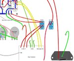
My switch only has 4 lugs but there are 6 connections needed between 2 switches for the layout. My thoughs were to use the two for on off on the right side of the switch then connect both AC connections to one on the left then connect the two going to the PCB to the other on the left. Am I thinking correctly? Sorry if this is a stupid question but Im still learning and this build is a bit out of my comfort zone.
My switch only has 4 lugs but there are 6 connections needed between 2 switches for the layout. My thoughs were to use the two for on off on the right side of the switch then connect both AC connections to one on the left then connect the two going to the PCB to the other on the left. Am I thinking correctly? Sorry if this is a stupid question but Im still learning and this build is a bit out of my comfort zone.