Presence Circuit and Shunt Resistor

FourT6and2

Well-known member
I'd like to discuss the pros/cons and theory behind each of these three presence circuits. Amp is a 50-watt JCM800 w/Jose mod. But focusing just on presence.

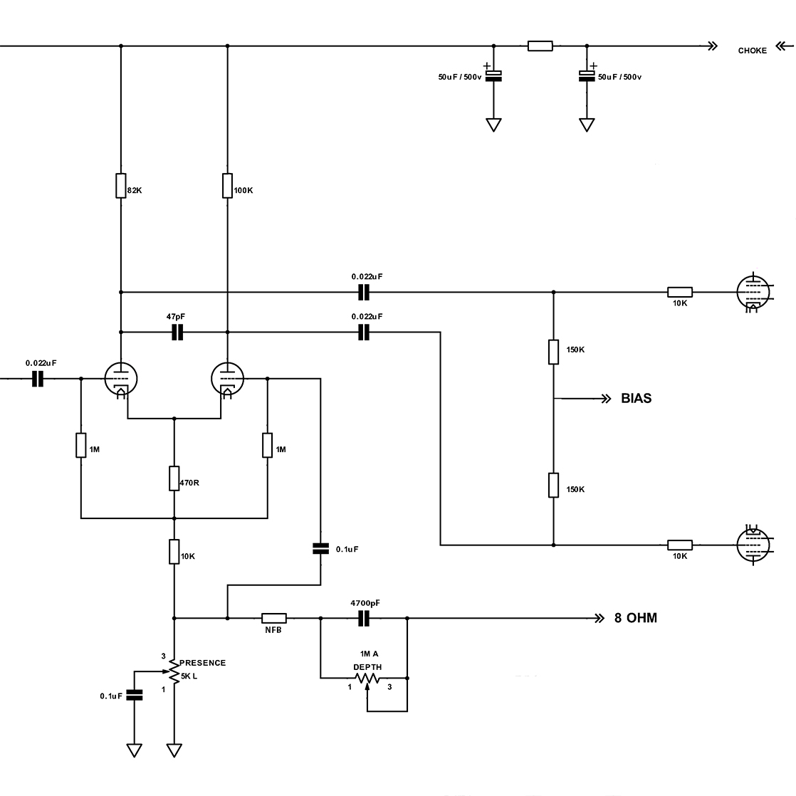
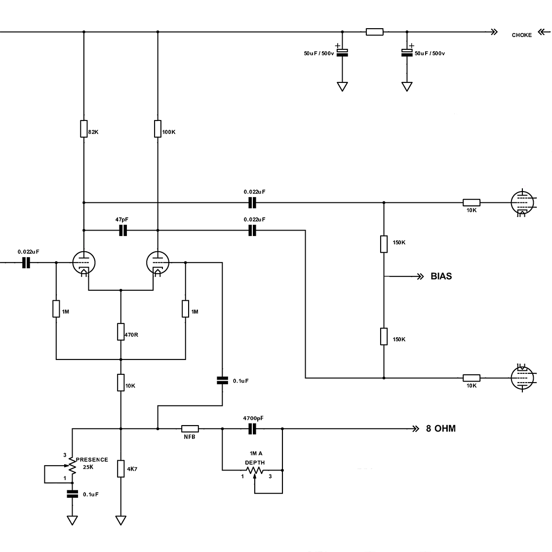
I'm asking because I'm familiar with Arrangement 1 and 2. In #1, the 5K presence pot acts as the end of the PI tail. In #2, a 25K pot is used and the presence cap is in series to ground, rather than parallel. And a 4K7 resistor is used to end the tail. But what about Arrangement #3? At first glance it appears to be a mistake. As though someone wired it up by accidentally combining the first two. But... I want to give the amp builder the benefit of the doubt and assume maybe I'm just not understanding something. And maybe the builder did it intentionally.

Arrangement 1

dfgrbf7-5745f9c8-3f1b-4577-884d-95e9ed6217b4.jpg


Arrangement 2

dfgrbf2-aeef898a-6306-4ae3-aa6a-e1f65fde4ed6.jpg


Arrangement 3

dfgrbf5-a1c70d40-d69e-474b-ab66-cb59da96035c.jpg
 
I had #3 that was stock in a '76 50W that Shea at Monomyth modded. I remember because he returned the pot and the 4k7 with the amp. And fwiw that amp sounded killer stock...and modded too.
 
I had #3 that was stock in a '76 50W that Shea at Monomyth modded. I remember because he returned the pot and the 4k7 with the amp. And fwiw that amp sounded killer stock...and modded too.

But would it actually sound different than #1? I would try it but all my stuff is in storage at the moment. What's the actual theory behind the two?
 
The way I see it the main differences between 1 and 3 are the NFB change due to the 'to ground' part of that voltage divider being cut in half, so less NFB since more of it is getting dumped to ground. And the pot could possibly be less noisy than 1. But the Presence would almost have to react differently and it seems like it would be a neutered Presence control.

And I think what my '76 50W had was probably #2 with a 5k pot. I didn't look at #3 closely enough. When I bought the amp; I checked it out, and sent it away to be modded so I didn't mess with the amp much. I remember it having a pleasant warmth but it was one of those 390v B+ amps.
 
#2 is what I do.

Treat #3 as a variable voltage divider where the pot is. The conductive branch referencing ground will always be in parallel with the cap but since the cap is so large, assume it’s a short circuit. If you do that, you can see the lower conductive branch won’t actually carry much current since the cap acts as an ac short for most frequencies. The top branch resistance is a variable resistor in series with the large cap which controls the series RC filter response to ground. So in a way it’s an odd method to have a series resistance with the cap to ground, but what’s even more odd is that series resistance in series to the cap is also in parallel with the 4.7k, so overall I think it wouldn’t be that efficient as a presence control at all.

To fix #3 I’d snip leg 1 to ground leaving it open circuit, and then it would be identical to #2
 
Last edited:
I wonder if someone just grabbed a 5K pot instead of 25K by mistake. Or if it was intentional to do it this way. But it couldn't have been a mistake of just grabbing the wrong pot because then it's also wired "wrong". The cap would need to be wired in series, not parallel as in #1 and #3. I dunno. It's confusing to me why someone would choose to do this.

I'll have to throw a 4K7 on my presence pot and see what it does.
 
Put a pot across your presence pot to understand what the varying resistance does. But as said, tunes the presence control frequency and NFB
 
Put a pot across your presence pot to understand what the varying resistance does. But as said, tunes the presence control frequency and NFB

Oh that's a good idea. I could throw a 10k linear pot wired as a variable resistor from Presence lug 3 to ground.
 
So it becomes a 2.42k pot and the taper will change. Could be intentional. More signal would go to ground with 2.42k vs 5k between NFB and ground. How much that will change the tone I can’t say. Seems like it would be less reactive on the sweep from 1-10.
 
I’ve not seen the arrangement in 3, it looks like an error to me. Or as Jeremy says, to provide a different sweep.

All these circuits need to be thought about in DC terms also, which sets the operating point of the tube as the presence pot arrangement is the ground reference for the PI.
 
I’ve not seen the arrangement in 3, it looks like an error to me. Or as Jeremy says, to provide a different sweep.

All these circuits need to be thought about in DC terms also, which sets the operating point of the tube as the presence pot arrangement is the ground reference for the PI.
I thought it was the PI cathode resistor (the 470R) that set the operating point? And you measure only across that resistor to calculate the current since the whole PI ground is 'lifted by the long tail' which is the 10k tail resistor. From there it could be sent straight to ground like in Vox amps with no NFB but they need something to create a voltage divider for NFB, hence the 4k7 shunt or just the 5k pot...or the 820R (no Presence) in BF Fenders.
 
I’ve not seen the arrangement in 3, it looks like an error to me. Or as Jeremy says, to provide a different sweep.

All these circuits need to be thought about in DC terms also, which sets the operating point of the tube as the presence pot arrangement is the ground reference for the PI.

I keep seeing that arrangement pop up from multiple companies/builders. It looks like an error to me too, but I just don't know now. Here's another similar error from Mojo Tone. Correct components (25K pot, 0.1uF cap, 4k7 shunt). But the cap is connected in parallel to ground instead of series, effectively mistakenly combining the two classic Presence circuits Marshall used.

The pot's lug 1 should not go to ground. It should connect to the wiper and the cap should be in series to ground. I spotted this in someone's recent DIY build. The made the change and said it sounded/operated better after the correction.

The second image is from Ceriatone. At least they got the Presence control right...

9C208C68-BA0A-4B43-8DB5-B359E02E922B.jpg


JCM800_2204Ceriatone.jpg
 
Last edited:
@FourT6and2 , on my screen it doesn't look like the pot in either schemo is grounded. Even tho they connect the left lug in the Ceriatone schemo it still doesn't look grounded. So it's only the 4k7 that is DC ground in both I think.

Edit: OK zooming in I can see that sliver of grey between the pot case and the lug so they did ground that end. Genius to use grey wire on top of grey pot cases in that layout. That's just a mistake imo but it's 25k in parallel with 4k7 so not as drastic as if it were the 5k pot. Just a NFB tweek there imo, maybe a tiny bit of noise when turning since there would be tiny amount of DC current thru it.

If I look at the schematic from Mojo for the same amp, they have it correct. But in the layout, it's incorrect. I think it's a mistake.

But 99% of people buying kits from them aren't going to use the schematic to build the amp. They are going to use the paint-by-numbers layout and they are going to make the same error. So, when I see a "big name builder" do the same thing on a hot-rodded circuit that's been floating around the net for 40 years, what am I to think...

Anyway, it's an interesting situation to see all these innocent errors carried over from schematics and layouts because the builder didn't double check.
 
So, when I see a "big name builder" do the same thing on a hot-rodded circuit that's been floating around the net for 40 years, what am I to think...
I see what you mean. I watched a video recently of I think Steve Fryette and at some point there was math and he talked us thru it. It was not pretty. I guess my point is not all these big name builders have all the college or EE skills as good as they just know amps.
 
I see what you mean. I watched a video recently of I think Steve Fryette and at some point there was math and he talked us thru it. It was not pretty. I guess my point is not all these big name builders have all the college or EE skills as good as they just know amps.

Well I'm certainly no engineer. I'm just saying... I see this kind of thing in production amps all the time and I don't know what to make of it.
 
Hope this would help. Simulation results of particular cases below. It's a simulation of EL34 PP and the frequency response is dependent on few components in the circuit. So compare results just relatively between screenshots. Parametrized is Presence pot, 10 steps in each circuit. NFB circuit like this one to have relatively flat bass response, the rest like in OP

CaseNFB.jpg

Case1.jpg

Case2.jpg

Case3.jpg
 
This shows, visually, why I like the first one (5k pot, cap in parallel, no shunt resistor). Only downside is DC on the pot. But really... who cares.

I still need to tack in a 4k7 shunt into my amp to see how it actually sounds in comparison.
 
Back
Top