FourT6and2
Well-known member
Just another variation on this design. What do y'all think? Values in parentheses are still up in the air: https://orig00.deviantart.net/7970/f/20 ... ckc5mf.jpg

FourT6and2":33em4ot3 said:Just another variation on this design. What do y'all think? Values in parentheses are still up in the air: https://orig00.deviantart.net/7970/f/20 ... ckc5mf.jpg
CrazyNutz":27pvlnqu said:I would use 1M linear for the gains, add a switch for the bright cap, and get rid of that standard depth control in favor of the CCV style.
Other than that looks good.
cyphervox":37o0lhbf said:Looks like a sweet Jose variant! Do you prefer passive loops? I think a secondary PPIMV would also be sweet for low-volume sessions. I have a Xenrelic custom with a similar configuration for the gain modes, but with a lossless loop. It's pretty sweet!
SpiderWars":xd0e74x0 said:My first thought was also a CCV-style depth, you could use a pull pot if you don't want another switch. You'll probably have to play with that resistor, seems MC used a few different values.
I don't have a good explanation why but I'd put that .001u snubber on the other side of the 68k grid stopper on V1.
I don't think it was always 27k, esp in the MC built ones but I could be wrong. Others here know for sure. I tried 27k/33k/39k/47k but in my amp (Ceriatone KK) I liked 82k. And I almost always used that switch position, with the 82k 'IN'.FourT6and2":1r89muli said:SpiderWars":1r89muli said:My first thought was also a CCV-style depth, you could use a pull pot if you don't want another switch. You'll probably have to play with that resistor, seems MC used a few different values.
I don't have a good explanation why but I'd put that .001u snubber on the other side of the 68k grid stopper on V1.
You're talking about the 27K used in the CCV Depth? What am I looking for regarding that resistor value? Does it depend on NFB or anything else or just a preference thing? I want to avoid another switch. So maybe a push/pull.
I've tried that snubber cap in a few different positions. Doesn't seem to make a huge difference. But I'm open to learning why it might be better to swap its position.
SpiderWars":h6e0asbz said:I don't think it was always 27k, esp in the MC built ones but I could be wrong. Others here know for sure. I tried 27k/33k/39k/47k but in my amp (Ceriatone KK) I liked 82k. And I almost always used that switch position, with the 82k 'IN'.FourT6and2":h6e0asbz said:SpiderWars":h6e0asbz said:My first thought was also a CCV-style depth, you could use a pull pot if you don't want another switch. You'll probably have to play with that resistor, seems MC used a few different values.
I don't have a good explanation why but I'd put that .001u snubber on the other side of the 68k grid stopper on V1.
You're talking about the 27K used in the CCV Depth? What am I looking for regarding that resistor value? Does it depend on NFB or anything else or just a preference thing? I want to avoid another switch. So maybe a push/pull.
I've tried that snubber cap in a few different positions. Doesn't seem to make a huge difference. But I'm open to learning why it might be better to swap its position.

There are amps that were modded with just a pull pot but I don't know the values used. The different values seem to focus the mids a little differently. I don't see why you couldn't use a pot for testing there.FourT6and2":316q3o7m said:SpiderWars":316q3o7m said:I don't think it was always 27k, esp in the MC built ones but I could be wrong. Others here know for sure. I tried 27k/33k/39k/47k but in my amp (Ceriatone KK) I liked 82k. And I almost always used that switch position, with the 82k 'IN'.FourT6and2":316q3o7m said:SpiderWars":316q3o7m said:My first thought was also a CCV-style depth, you could use a pull pot if you don't want another switch. You'll probably have to play with that resistor, seems MC used a few different values.
I don't have a good explanation why but I'd put that .001u snubber on the other side of the 68k grid stopper on V1.
You're talking about the 27K used in the CCV Depth? What am I looking for regarding that resistor value? Does it depend on NFB or anything else or just a preference thing? I want to avoid another switch. So maybe a push/pull.
I've tried that snubber cap in a few different positions. Doesn't seem to make a huge difference. But I'm open to learning why it might be better to swap its position.
Some of the layouts I've seen show a pot, but yeah I don't have room in the chassis for another pot/switch. So I'd have to either hardwire a resistor in or use a push/pull. Can you describe the actual sonic difference between the various values? Or I can alligator clip a pot in and just play around with it until I find a value I like, then solder in a resistor of that value.
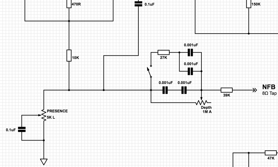
Not 3 for sure, 2 looks right but there was a 3-way switch and several 33k to select 33k/66k/99k...I think lol.FourT6and2":2qj77ucs said:Also, with the CCV style Depth, does the NFB resistor go before or after the pot? I've got a few different schematics but they're all showing the Depth location in different spots.
1, 2, or 3 (ignore resistor value for now)?
SpiderWars":9h86xu2v said:Not 3 for sure, 2 looks right but there was a 3-way switch and several 33k to select 33k/66k/99k...I think lol.
I've never owned one just going form pics/info from when I had the KK that had allegedly been modded to CCV specs (not). I think of the two switches as the Presence switch and the Depth switch (simpleton lol). The Depth switch is the switch you have drawn and my understanding is the Presence switch was the NFB switch with all the 33ks.FourT6and2":32i62c5f said:SpiderWars":32i62c5f said:Not 3 for sure, 2 looks right but there was a 3-way switch and several 33k to select 33k/66k/99k...I think lol.
Are you talking about on an actual CCV? I had a CCV it didn't have any of this stuff.
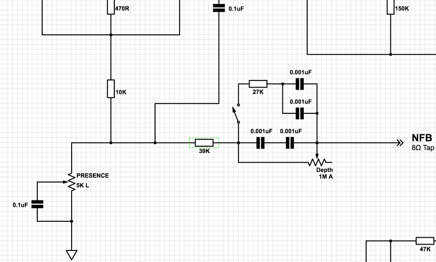
Thanks for the explanation on that snubber. It didn't look right but I didn't know why.fusedbrain":2lhh4e8s said:re: the NFB - # 3 is wrong. 1 or 2 will work, but will sound different. I believe that placing the 39k before the depth network will change the cutoff frequency of the high pass filter vs what you would expect to get with just the pot and the 500pf / .002 caps.
re: the .001 / 68k position. I am assuming you are trying to snub the fizzies here vs using a plate bypass cap. If the cap is placed after the resistor, you create a low pass filter with a corner frequency of 2.3k with the 68k resistor, and approx 1k with the 150k. This is probably much to low. With the cap before the resistor, i believe the cuttof freq. will be much higher while still snubbing the fizz, as seen in the Fortin Cali / Ceriatone Yeti / Chuppa.
fusedbrain":3oxk31jc said:re: the NFB - # 3 is wrong. 1 or 2 will work, but will sound different. I believe that placing the 39k before the depth network will change the cutoff frequency of the high pass filter vs what you would expect to get with just the pot and the 500pf / .002 caps.
re: the .001 / 68k position. I am assuming you are trying to snub the fizzies here vs using a plate bypass cap. If the cap is placed after the resistor, you create a low pass filter with a corner frequency of 2.3k with the 68k resistor, and approx 1k with the 150k. This is probably much to low. With the cap before the resistor, i believe the cuttof freq. will be much higher while still snubbing the fizz, as seen in the Fortin Cali / Ceriatone Yeti / Chuppa.
fusedbrain":15jecrhb said:Yes, that's basicaly what I was getting at: the cap is not placed after a resistor to create a high pass filter. Just snubbing signal directly to ground.
I don't know about the order of the resistors and bypass cap, but I've read where some people ( psychodave etc) prefer the snubbed cap vs the plate bypass approach, saying the plate bypass method can make the amp sounds lifeless.
The Friedman amps make extensive use of plate bypass caps and can sound kinda smooth / dull until you signicantly reduce the amount of NFB.
An amp using the snubbed cap method is on my list of things to test.
FourT6and2":2pmwyagy said:cyphervox":2pmwyagy said:Looks like a sweet Jose variant! Do you prefer passive loops? I think a secondary PPIMV would also be sweet for low-volume sessions. I have a Xenrelic custom with a similar configuration for the gain modes, but with a lossless loop. It's pretty sweet!
I prefer tube-buffered loops but a passive loop is just easier to build haha. I only use a delay pedal in the loop and it's buffered, so it seems to work just fine. No need for a PPIMV as these amps sound great at low volume thanks to the zeners.