H
Holy-diver
Well-known member
This might be a dumb question but I can’t find any reliable info on it. What reading am I looking for for the HP KT88 on the multimeter?

I bet all the KT88 HPV UUs probably run around 500v give or take. I'd just base it off that. I've owned the same model of quite a few amps and they're always basically the same plate voltage even when they're different years.Yeah, I’m new to biasing and I couldn’t find any tech sheets with plate voltage or anything and I don’t know how to check. Then I was reading that bogner recommends doing it while it’s super hot because it drifts up. Biasing my ceriatone was super easy comparatively and I don’t want to fuck anything up
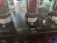
There are test point and pots for both pairs of tubes, ground is the middle one. It’s pretty easy to do all you have to take off is the back platenice thread.
I have EL34 and simple multimeter.
how exactly i can check that my bias Is good from stock and how i can adjust it if its not good? maybe someone have link to nice YouTube video about how do this?
or please write steps for me. I hope its not hard and dangerous.
thanks
sorry, I see two 3 pins grounded sockets, screws near the tubes and two white bias adjust knobs.There are test point and pots for both pairs of tubes, ground is the middle one. It’s pretty easy to do all you have to take off is the back plate
this labels is a test points?The center one is ground, then the pairs are v7 and v10 and v8 and v9. It’s labeled on mine
I assume the uber ultra test points are across 1 ohm resistors on the cathode of the power tubes? I don’t see it mentioned in the manual or this thread.sorry, I see two 3 pins grounded sockets, screws near the tubes and two white bias adjust knobs.
one cabel I connect to ground and where connect second?
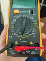
and please look, my multimeter setup right or wrong? thanks
Thanks. I will try it soon today.I assume the uber ultra test points are across 1 ohm resistors on the cathode of the power tubes? I don’t see it mentioned in the manual or this thread.
If so you have the correct setting (200mv scale) but move your red test lead to the socket on the far right (volts/ohms/capacitance)
For your reading to mean anything though, we need to know what value resistor you’re reading voltage drop across (you can read resistance between one of the bias points and the ground point - measure resistance with multimeter leads touched together first to see resistance of the leads and factor this in).
Also need plate voltage as mentioned above, this will change based on wall voltage and the bias setting so I don’t really like to make assumptions on what it might be. You need to open the amp with it powered on and out of standby for that, I wouldn’t attempt unless you know what you’re doing.
No danger, there should only be millivolts on those connections. Ideally pretty similar measurements for each oneThanks. I will try it soon today.
but its not dangerous for me or amp/tubes when I try measure it with multimeter? because people said its not hard. hope so
Black to ground
Red (to switch to volts) and connect it to other two pins and save results?
Big thanks!You need the plate voltage at your wall voltage to reliably bias anything. Using someone else’s means nothing if the wall voltage isn’t identical and the model is identical - the KT88 models are different from the EL34 models to my understanding as they’re different transformers.
Using ohms law:
P=IV
Take the max wattage of the tube, 25W by today’s standards, multiply by 0.7 for 70% max plate dissipation in watts, divide by the plate voltage, and that’s your max safe quiescent bias point with no signal in the amplifier and after tubes have been warmed up for over an hour.
25W *0.7 =17.5 W
17.5W / 520V = 33.6 mA
Across a 1 ohm resistor on the cathode that equates to 33.6mV for plate and screen grid currents both.
If you have 1K screen grid resistors then the screen grids are:
520V * 520V / 1K = 1.05W of your 17.5W max.
Therefore your actual plate current is:
(17.5W - 1.05W) / 520V = 3.1 mA of the 33.6mA you originally calculated. So if you wanted your plate current to be 33.6mA actual, you’d need to set at 33.6mA + 3.1mA or 36.7mA. Again this is because cathode resistors capture plate and screen grid currents combined. People usually forgo this step because 3mA is buffer for added tube life.
If your amp has triode or pentode mode capabilities you must put it in triode mode first and then the bias current across the cathode resistor will closely match the plate current.
This is the absolute maximum you should run for your tubes. This doesn’t mean set them at this level unless you don’t mind faster wear and shorter lifespan. I recommend 60% typically for maximum plate dissipation.
You can also calculate the screen grid current by measuring the voltage drop across the screen grid resistor divided by the 1K typical screen grid resistor to get the actual current directly which you subtract from the cathode current to get the actual plate current - but this requires opening up the amp.
IF YOU DONT WARM THE TUBES FIRST YOU WILL EXPERIENCE BIAS RUNAWAY ESPECIALLY WITH NEW TUBES NOT BURNED IN WHEN BIASING CLOSE TO 70%!
gusy, got measuresYou need the plate voltage at your wall voltage to reliably bias anything. Using someone else’s means nothing if the wall voltage isn’t identical and the model is identical - the KT88 models are different from the EL34 models to my understanding as they’re different transformers.
Using ohms law:
P=IV
Take the max wattage of the tube, 25W by today’s standards, multiply by 0.7 for 70% max plate dissipation in watts, divide by the plate voltage, and that’s your max safe quiescent bias point with no signal in the amplifier and after tubes have been warmed up for over an hour.
25W *0.7 =17.5 W
17.5W / 520V = 33.6 mA
Across a 1 ohm resistor on the cathode that equates to 33.6mV for plate and screen grid currents both.
If you have 1K screen grid resistors then the screen grids are:
520V * 520V / 1K = 1.05W of your 17.5W max.
Therefore your actual plate current is:
(17.5W - 1.05W) / 520V = 3.1 mA of the 33.6mA you originally calculated. So if you wanted your plate current to be 33.6mA actual, you’d need to set at 33.6mA + 3.1mA or 36.7mA. Again this is because cathode resistors capture plate and screen grid currents combined. People usually forgo this step because 3mA is buffer for added tube life.
If your amp has triode or pentode mode capabilities you must put it in triode mode first and then the bias current across the cathode resistor will closely match the plate current.
This is the absolute maximum you should run for your tubes. This doesn’t mean set them at this level unless you don’t mind faster wear and shorter lifespan. I recommend 60% typically for maximum plate dissipation.
You can also calculate the screen grid current by measuring the voltage drop across the screen grid resistor divided by the 1K typical screen grid resistor to get the actual current directly which you subtract from the cathode current to get the actual plate current - but this requires opening up the amp.
IF YOU DONT WARM THE TUBES FIRST YOU WILL EXPERIENCE BIAS RUNAWAY ESPECIALLY WITH NEW TUBES NOT BURNED IN WHEN BIASING CLOSE TO 70%!