You are using an out of date browser. It may not display this or other websites correctly.
You should upgrade or use an alternative browser.
You should upgrade or use an alternative browser.
Ceriatone Chupacabra effects loop/tone changes?
- Thread starter ledvedder
- Start date
ledvedder
Well-known member
peckhart":15jsewy6 said:Bringing this one back up. Curious if OP resolved the loop issues and if so how.
See about 8 or 9 posts up. I installed a metro zero loss loop.
FourT6and2
Well-known member
CrazyNutz":3odisolm said:33k on the slope will have better mids, 47k sounds a bit scooped to me. A nice compromise is 39k.
Yeah, "better" is subjective. 47K is a bit scooped. But I think it sounds good in this amp. 33K is a bit honky. 39K or 36K are both good compromises. I prefer 47K or 39K myself.
And I agree on the PPIMV thing. Not a useful mod in this amp. It's got a master volume already and two gain pots. In Plexi mode, just play with the gains and you'll get great cranked sounds at low volumes. A PPIMV is gonna mess with the PI topology of this amp and limit the usefulness of the tone stack when you turn it down. But hey, play around with it, OP.
For the unused hole in the rear of the chassis now, you could throw either a switch or a mini pot in there to have a variable slope resistor. And to see how you like one slope vs another, just wire in a pot in place of the resistor and you can just turn it until it sounds good. Then measure the pot to see what value resistor to use.
After doing it blind for a week or two, I measured the pot. Guess what the value was lol
ledvedder
Well-known member
FourT6and2":1z7b9s37 said:CrazyNutz":1z7b9s37 said:33k on the slope will have better mids, 47k sounds a bit scooped to me. A nice compromise is 39k.
Yeah, "better" is subjective. 47K is a bit scooped. But I think it sounds good in this amp. 33K is a bit honky. 39K or 36K are both good compromises. I prefer 47K or 39K myself.
And I agree on the PPIMV thing. Not a useful mod in this amp. It's got a master volume already and two gain pots. In Plexi mode, just play with the gains and you'll get great cranked sounds at low volumes. A PPIMV is gonna mess with the PI topology of this amp and limit the usefulness of the tone stack when you turn it down. But hey, play around with it, OP.
For the unused hole in the rear of the chassis now, you could throw either a switch or a mini pot in there to have a variable slope resistor. And to see how you like one slope vs another, just wire in a pot in place of the resistor and you can just turn it until it sounds good. Then measure the pot to see what value resistor to use.
After doing it blind for a week or two, I measured the pot. Guess what the value was lol
How do you get any overdrive when in 60s mode? The manual says to crank the master, then use gain 1 as the volume. But, this gets way to loud before it starts to get any overdrive.
That's interesting about the slope value. Thanks!
ledvedder":1sjxgr8t said:peckhart":1sjxgr8t said:Bringing this one back up. Curious if OP resolved the loop issues and if so how.
See about 8 or 9 posts up. I installed a metro zero loss loop.
I don't know how i missed that. How do you like it?
ledvedder
Well-known member
peckhart":3lfk5l7b said:ledvedder":3lfk5l7b said:peckhart":3lfk5l7b said:Bringing this one back up. Curious if OP resolved the loop issues and if so how.
See about 8 or 9 posts up. I installed a metro zero loss loop.
I don't know how i missed that. How do you like it?
It works great. I'm not hearing any difference when I have pedals plugged into the loop vs nothing plugged in. Unlike the original insert loop, which sucked all kinds of highs and some volume when I plugged anything into it.
CrazyNutz
Well-known member
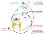
ledvedder":1uu2bbev said:After looking at the board layout, I'm a bit confused about the ppimv install. The Chupa has 110k instead of 220k resistors. Plus, there are 5.6k resistors at pin 5 of both power tubes. So, with the dual 250k pot, Nik from Ceriatone told me to use 330k resistors on the pot instead of 2.2meg resistors. But, besides the 110k resistors, do I also remove the 5.6k resistors?
He also told me not to put the small jumper wire on the pot.
You keep the 5.6k resistors in place. Those are there to prevent oscillation, and they also affect the tone, so removing them will change the tone. (contrary to some)
This is how you would wire it up on the chupa.
Attachments
ledvedder
Well-known member
CrazyNutz":3bko7qap said:ledvedder":3bko7qap said:After looking at the board layout, I'm a bit confused about the ppimv install. The Chupa has 110k instead of 220k resistors. Plus, there are 5.6k resistors at pin 5 of both power tubes. So, with the dual 250k pot, Nik from Ceriatone told me to use 330k resistors on the pot instead of 2.2meg resistors. But, besides the 110k resistors, do I also remove the 5.6k resistors?
He also told me not to put the small jumper wire on the pot.
You keep the 5.6k resistors in place. Those are there to prevent oscillation, and they also affect the tone, so removing them will change the tone. (contrary to some)
This is how you would wire it up on the chupa.
Thanks. Someone also mentioned 2M2 safety resistors? Where would they go, if needed?
CrazyNutz
Well-known member
ledvedder":ntncgvr4 said:Thanks. Someone also mentioned 2M2 safety resistors? Where would they go, if needed?
The 2m2 (2.2m) are being replace with the 330k's on the pots.
They are considered "safety resistors" because if the pot wiper fails, you'll still have bias current going to the tube via these resistors. Keeping the tube from going into thermonuclear meltdown
ledvedder
Well-known member
CrazyNutz":2f0eeuyn said:ledvedder":2f0eeuyn said:Thanks. Someone also mentioned 2M2 safety resistors? Where would they go, if needed?
The 2m2 (2.2m) are being replace with the 330k's on the pots.
They are considered "safety resistors" because if the pot wiper fails, you'll still have bias current going to the tube via these resistors. Keeping the tube from going into thermonuclear meltdown
OK thanks. I guess I should tell the guy on the metro forums who's telling me I still need the 2M2 resistors.
scottosan
Well-known member
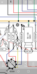
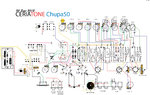
It is not shown on your pic. It’s further upstream.ledvedder":12a96vf9 said:Which one of these 10K resistors is the PI dropping resistor?
On a separate note, I noticed Nic ommitted the dropping resistor between the PI filtering and the subsequent stage filtering caps on both the 50 and 100. Doesn’t make sense
ledvedder
Well-known member
scottosan":36369zve said:It is not shown on your pic. It’s further upstream.ledvedder":36369zve said:Which one of these 10K resistors is the PI dropping resistor?
On a separate note, I noticed Nic ommitted the dropping resistor between the PI filtering and the subsequent stage filtering caps on both the 50 and 100. Doesn’t make sense
Hmm, OK. Here is the full layout.
Attachments
scottosan
Well-known member
it the 10k 2w between the positive terminals of the dual can cap with the letter “P”.ledvedder":pdh4xbz4 said:scottosan":pdh4xbz4 said:It is not shown on your pic. It’s further upstream.ledvedder":pdh4xbz4 said:Which one of these 10K resistors is the PI dropping resistor?
On a separate note, I noticed Nic ommitted the dropping resistor between the PI filtering and the subsequent stage filtering caps on both the 50 and 100. Doesn’t make sense
Hmm, OK. Here is the full layout.
May I ask what this is for?
ledvedder
Well-known member
scottosan":3i3tty7m said:it the 10k 2w between the positive terminals of the dual can cap with the letter “P”.ledvedder":3i3tty7m said:scottosan":3i3tty7m said:It is not shown on your pic. It’s further upstream.ledvedder":3i3tty7m said:Which one of these 10K resistors is the PI dropping resistor?
On a separate note, I noticed Nic ommitted the dropping resistor between the PI filtering and the subsequent stage filtering caps on both the 50 and 100. Doesn’t make sense
Hmm, OK. Here is the full layout.
May I ask what this is for?
This is to bring the B+ voltage back up after installing the metro loop.
scottosan
Well-known member
how much of a drop did you take. Are you noticing any detrimental? I assume the drop is minimalledvedder":4rmj7ak0 said:scottosan":4rmj7ak0 said:it the 10k 2w between the positive terminals of the dual can cap with the letter “P”.ledvedder":4rmj7ak0 said:scottosan":4rmj7ak0 said:It is not shown on your pic. It’s further upstream.ledvedder":4rmj7ak0 said:Which one of these 10K resistors is the PI dropping resistor?
On a separate note, I noticed Nic ommitted the dropping resistor between the PI filtering and the subsequent stage filtering caps on both the 50 and 100. Doesn’t make sense
Hmm, OK. Here is the full layout.
May I ask what this is for?
This is to bring the B+ voltage back up after installing the metro loop.
scottosan
Well-known member
11v is not worth changing it. A few volts variation in wall power can swing B+ledvedder":bochw68z said:It dropped about 11v. I'm really not sure if I'm noticing anything bad, but something seemed different last night. Maybe it was just ear fatigue. It seemed a bit bassy and mushy, and that was with the bass and resonance both at only 2 or so. Could just be me.