You are using an out of date browser. It may not display this or other websites correctly.
You should upgrade or use an alternative browser.
You should upgrade or use an alternative browser.
Ceriatone Chupacabra effects loop/tone changes?
- Thread starter ledvedder
- Start date
scottosan
Well-known member
instead of going to the PI, it goes to the volume, wire like a traditional volume control then the wire of the return volume to the PI, but I have said before, this is not necessary to get unity levels with you effects. On a single channel amp it’s kind of a waste. If it were a multichannel amp then it could be used as a global master volumeledvedder":3809xj64 said:Now to just figure out how to install it after the switch.
ledvedder
Well-known member
scottosan":1u7qaxc8 said:instead of going to the PI, it goes to the volume, wire like a traditional volume control then the wire of the return volume to the PI, but I have said before, this is not necessary to get unity levels with you effects. On a single channel amp it’s kind of a waste. If it were a multichannel amp then it could be used as a global master volumeledvedder":1u7qaxc8 said:Now to just figure out how to install it after the switch.
That's true, and since I'm liking how the amp sounds, I probably don't need it. But, I am enjoying learning about it.
scottosan
Well-known member
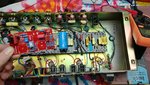
If there aren't any traces on either side of the board where the jacks are, you may be able to drill some mounting holes and use stand offs assuming you have enough clearance in both straddling the socket and high enough to clear the main boardledvedder":380ax2rz said:Ok guys, I've removed the jacks from the metro board. Any recommendations about where I should place the board?
FourT6and2
Well-known member
You could place it on the sidewall of the chassis before the preamp, like the DC Heater board is mounted on the opposite end near the power transformer. Mount it on standoffs. You'd have to pay close attention to lead dress. Other option is to mount it on tall standoffs using one or more of the preamp board mounts. Just unscrew one of the bolts on the board and screw in another, identical, standoff to that one.
fusedbrain
Well-known member
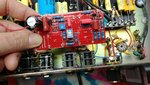
Nice job getting the jacks off the board!! You're almost there.
Now that the jacks are separate from the board, I would...
1: use CrazyNutz idea of short pieces of buss wire to attach the board to the jacks.
Or
2: see if you can lay out 2 sets of matching holes in the metro loop board and in the Ceriatone board in the areas I marked on your pic, and use 2 stand-offs to mount the board there.
The idea of mounting the board on the side wall is valid as well, but the first 2 ideas keep the leads as short as possible.
Attachments

harddriver
Well-known member
What's that pot on the back of the chassis? Is that the pussy trimmer pot? Why don't you move that pot over to the right side(drill a new hole) of then you would have plenty of room to locate your Metro loop board and jacks whre you want them.
psychodave
Well-known member
I think they designed the board so that any open areas are basically a shield (ground). So you cant relocate the holes unless you countersink the outside of the holes to remove the ground.scottosan":2djtz69s said:If there aren't any traces on either side of the board where the jacks are, you may be able to drill some mounting holes and use stand offs assuming you have enough clearance in both straddling the socket and high enough to clear the main boardledvedder":2djtz69s said:Ok guys, I've removed the jacks from the metro board. Any recommendations about where I should place the board?
CrazyNutz
Well-known member
ledvedder":2bah0l3u said:Ok guys, I've removed the jacks from the metro board. Any recommendations about where I should place the board?
Flip it upside down, use buss wire to connect to the jacks, and you're done. The 8 pieces of buss wire will hold the board.
Caveat: if you go this route you may want to hot glue a plastic sheet on the back of the loop board, to make sure it does not short out on the headshell shielding.
ledvedder
Well-known member
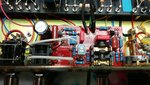
Here's what I was able to do with my limited skills at this point. I kept one jack connected to the board. I put the other jack in one of the speaker jack holes. Used buss wire to connect that jack to the board. Now I have to find something to plug up the old effects loop hole.
Attachments
scottosan
Well-known member
good job. if you have a lowes or home depot, go over to where they have the specialty screws, washers etc.. in those drawers and you will see both chromed or black plastic plugs.ledvedder":1to59lhw said:Here's what I was able to do with my limited skills at this point. I kept one jack connected to the board. I put the other jack in one of the speaker jack holes. Used buss wire to connect that jack to the board. Now I have to find something to plug up the old effects loop hole.
Something like this:
https://www.homedepot.com/p/Everbilt-3- ... /100338326
Just measure the hole
I'd also buy a new cliff jack with lugs and rewire the bus wire through the lugs with no slack as to provide more support for the board. I's even get some clear silicone and hit it in a few spots where the board is up against the chassis. More support the better
ledvedder
Well-known member
scottosan":15l3qgm3 said:good job. if you have a lowes or home depot, go over to where they have the specialty screws, washers etc.. in those drawers and you will see both chromed or black plastic plugs.ledvedder":15l3qgm3 said:Here's what I was able to do with my limited skills at this point. I kept one jack connected to the board. I put the other jack in one of the speaker jack holes. Used buss wire to connect that jack to the board. Now I have to find something to plug up the old effects loop hole.
Something like this:
https://www.homedepot.com/p/Everbilt-3- ... /100338326
Just measure the hole
I'd also buy a new cliff jack with lugs and rewire the bus wire through the lugs with no slack as to provide more support for the board. I's even get some clear silicone and hit it in a few spots where the board is up against the chassis. More support the better
Cool, I'll check those out. Thanks for all your help.
CrazyNutz
Well-known member
ledvedder":166sjn32 said:Next upgrade is the larmar ppimv that I have all the parts for. And maybe messing with the slope resistor value. I'm curious what 33k sounds like compared to the 47k that's in the amp.
33k on the slope will have better mids, 47k sounds a bit scooped to me. A nice compromise is 39k.
As for the PPIMV, not sure you're going to get a lot of usefulness from it. Possibly a better tone at lower volumes.
Either way experimentation is always fun, give it a shot
CrazyNutz
Well-known member
ledvedder":1hh6s568 said:Here's what I was able to do with my limited skills at this point. I kept one jack connected to the board. I put the other jack in one of the speaker jack holes. Used buss wire to connect that jack to the board. Now I have to find something to plug up the old effects loop hole.
Nice great job. BTW, you can get little plastic hole plugs to fill that hole. I get mine at ACE hardware.
ledvedder
Well-known member
After looking at the board layout, I'm a bit confused about the ppimv install. The Chupa has 110k instead of 220k resistors. Plus, there are 5.6k resistors at pin 5 of both power tubes. So, with the dual 250k pot, Nik from Ceriatone told me to use 330k resistors on the pot instead of 2.2meg resistors. But, besides the 110k resistors, do I also remove the 5.6k resistors?
He also told me not to put the small jumper wire on the pot.
He also told me not to put the small jumper wire on the pot.