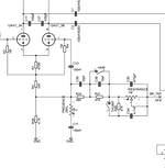
Isn't this a weird version of the the Thump control? All it's doing is reducing NFB resistance. It's not actually affecting the depth capacitance value.
Normally, you have that 47K and 4700pF in series after the switch, with the 470pF always in circuit. And when you flip the switch, it puts the additional 47K in series with the NFB resistor, raising the total value, along with the additional 4700pF, again raising the total value of the depth cap. I've not seen it used in this way, where the switch is bypassing just the additional resistor. It's kind of weird unless someone is trying to LOWER the total NFB resistance instead of RAISE it when the switch is engaged, while NOT affecting the depth capacitance. So it's not really a Thump control. It's just a NFB resistor switch.
Typically on Fortins and Camerons and Gowers and other hot-rodded builds, you've got a 470pF cap always in-circuit on the pot. Then the switch ADDS (not subtracts) an additional resistor AND cap.
As it looks in this schematic, total NFB resistance is 133K, with 470pF + 4700pF depth caps (totaling 5,170pF). Then when switch is engaged, all it does is reduce NFB to 86K?
OP where did you find this schematic? It looks like it's from the Fortin Cali schematic from SLO Clone. And are you sure it was drawn correctly and the switch shouldn't actually be in series before the 47K instead of bypassing it? You gotta be careful when you use schematics drawn by other forum members. There are often simple mistakes like this. That 47K should be in series after the switch, not in parallel with it IMO.