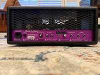
2004 SLO w/Deyoung Transformers versus New Bad SLO vid.

  • Thread starter Thread starter harddriver
  • Start date Start date
It's simply for noise. And mostly for preamp tubes, not counting the PI position. Power tubes don't benefit from DC heaters, as far as I know.

I think what you're talking about might be DC elevated heaters. This is something different. And it's usually done to reduce the heater-to-cathode voltage differential in cathode follower preamp tube positions. Mostly in Marshall-style circuits. The cathode follower can be hard on preamp tubes, causing modern tubes with spiral filaments to die quicker.

The heater circuit's center tap is typically referenced to 0V (chassis ground). When you reference the heater's center tap to some higher, elevated DC point (like 45v DC, typically an already filtered/smoothed node), the AC heater circuit "floats" on top of a DC-referenced voltage instead of 0V/ground. This elevation helps reduce the strain on tubes in cathode follower positions. It can help reduce some noise, but it's really not intended to do that and the heaters are still AC.

Think of a sine wave. It's oscillating from +3.15v to -3.15, centered at 0v.

When you elevate the heaters, 0v is no longer the center reference. You reference the wave to... let's say +45v DC. Now your "center" is +45v. So the 6.3v AC heater circuit oscillates from +48.35v DC to -41.85v DC, with 45v DC being the new "0". The AC wave is still only 6.3v, it's just floating higher.

Because the new reference is +45v, the DC voltage differential between the cathode and the heater circuit is 45v lower, thus lowering the stress on the tube. The maximum voltage differential is listed in the tube's data sheet. So it's easy to calculate if you need to elevate the heaters and by how much.
Yes, this is correct, and coincidentally the cathode follower voltage at the fx loop send in the OG SLO is around 210v, and 12ax7s with spiral filaments will hum like a mofo and die a quick death in this case.
Max heater to cathode voltage for those tubes is typically 180v.
The BAD SLO solves this issue.

Many Marshall style circuits benefit from higher preamp voltages, so using elevated heaters in these designs will allow for the use of most current production tubes without issue.
 
Am I wrong in thinking a NFB knob would help open up the SLO, shifting the mids?

Yes, absolutely. I add a NFB control to all my SLO mods. It makes a massive difference and really opens the amp up. Once you turn it up, and then set it back to stock value, it sounds super dark and woofy in comparison. SLO’s have a lot of NFB stock. 39k NFB resistor and it’s on the 8 ohm tap.

I use the line out level knob hole to add the NFB. So no holes get drilled with the mod. I also add a 3 way depth frequency switch.

How many have you modded now?

That’s a good question. Actually been a lot that I’ve done now. Both 100’s and 30’s.
 

Attachments

  • IMG_5555.jpeg
    IMG_5555.jpeg
    3.8 MB · Views: 59
Yes, I hear a difference in sound, but why would anyone assume the difference is due to the transformers? These two amplifiers have so many differences in their components, and then there's the aging process to consider. When you also consider that different tubes can color the sound differently, the transformer hypothesis sounds rather far-fetched.
Why is it far fetched? 2 transformers wound to similar specs be different companies will sound different
 
I can always tell when an engineer of any discipline gets involved in any gear conversation. They simply take on a very condescending and 'know it all' attitude. That's fine; engineers aren't dumb by any stretch. But, you also don't know everything, do you?
I'll give you an example. A very smart individual on this forum stated that, a 68 Marshall clone, with the exact same modern resistor/cap type/ and VALUES with the same modern reproduction transformers created to mimic 1968 Marshall Dagnalls would sound IDENTICAL to a real deal 1968 Plexi. There should be no difference between them, IF the same exact layout, type parts, wiring, pots, chassis, layout etc etc were used.
Except, when this theory was actually put to the test and this smart engineer actually A/Bd a great clone with Merren iron and all the great parts to a real 68 Plexi, the vintage Plexi blew the clone out of the water. It wasn't close; the clone sounded flat and uninspiring by comparison.

I get that you consider the heaters, and pots to also contribute to the tone and while I agree to some extent, I do not agree that it contributes to anywhere CLOSE to the extent the degree of an output transformer change. I've swapped OTs in amps and the change in tone is very apparent and obvious to my ears.
We'll just have to agree to disagree. If Dave Friedman doesn't agree, well that's ok too. I could care less.
I hope you feel better now that you’ve properly blown off some steam about those incompetent engineers. I don't mind. Just one more question: Are you here on Rig Talk solely to get validation for your statements, or are you interested in a dialogue? I thought rig-talk is about discussions.

I also swapped OT, but the difference in sound depends on the quality of the design and the materials used within the OT. If you swap out a badly designed OT, than it's just obvious that the sound will improve. The sound is the result of the design and the quality of the materials used. Heyboer and BAD are not known for bad designs and cheap materials, especially when the goal is to clone the OT of an iconic amplifier.
 
Last edited:
Why is it far fetched? 2 transformers wound to similar specs be different companies will sound different
Yes, it's the proximity to the corporate logo that does it. The laminations learn they're in a DeYong transformer and behave differently. You have to be careful - if you put them too close to other Heyboer transformers, for example stacking new SLOs with old ones, the DeYoungs will pick up the lazy ways of the Heyboers resulting in a less open and detailed sound.
 
Why is it far fetched? 2 transformers wound to similar specs be different companies will sound different
Interesting question: 2 transformers wound to similar spec by the same company on different days by different persons may sound a little different, too? Now we get into production territory...
 
Just personal, but I often ask “why do a comparison video through IRs?”
Yup - it's putting a lot of weight not only on the specific IR selected, but on the line-out behavior of the amp/load device. That's not really what either of these amps were designed for.
 
I think some rectifier tubes are directly heated, but I don't believe I've seen this done with octal-based power tubes in Class AB guitar amps. Maybe it's been done before, but I'm unaware of it.

The change from direct heated cathode tubes to indirect heated cathode tubes appears to happen somewhere around 1940 (after a very quick bit of internet research), so no surprise you haven't run into them in a guitar amplifier. Everything we commonly use have separate heaters.
 
I hope you feel better now that you’ve properly blown off some steam about those incompetent engineers. I don't mind. Just one more question: Are you here on Rig Talk solely to get validation for your statements, or are you interested in a dialogue?

I also swapped OT, but the difference in sound depends on the quality of the design and the materials used within the OT. If you swap out a badly designed OT, than it's just obvious that the sound will improve. The sound is the result of the design and the quality of the materials used. Heyboer and BAD are not known for bad designs and cheap materials, especially when the goal is to clone the OT of an iconic amplifier.
Unlike most engineers I know, the individual you are attacking has actual real world experience,not just "on paper this is how it works" bullshit. The jury decided long ago that in this instance, the original transformer used in the SLO does indeed make a large difference as it does in all amplifiers. You may not have the ear to discern the difference regardless of how book smart you are. There are good and bad engineers and all the good ones admit they don't know everything and seek the opinions of others. I can tell what kind of engineer you are from your posts. Not the type I'd hire.
 
https://tubemaze.info/sound-of-rectifier/

"Sonic differences in rectifiers has always fascinated me, and I have figured SOME of it out (but not all by any means!) The first huge variable as to how different rectifiers have a unique sonic signature from each other is basic construction type. Common tube rectifiers developed in the 1930s and 1940s such as USA types 5U4, 5R4, 5V3, WECO 274B etc, and U.K. / European rectifiers such as the legendary U52 are all what is known as “filamentary cathode” or “directly heated” types. Just like the legendary audio triodes like type 45 and type 300B, the directly heated/filamentary cathode rectifiers (5U4 etc) use a thoriated tungsten cathode that is ALSO the heater for the tube. When heater voltage is applied to a directly heated/filamentary cathode rectifier, it is able to produce DC voltage almost immediately. More about that issue later. The other main type of rectifier is the Indirectly Heated type such as GZ34/5AR4, 5V4, GZ37, 6X5 etc etc. These rectifier tubes have a heater and a cathode that are two separate units in the tube, electrically speaking. They use a traditional sleeved cathode just like KT88 etc; the cathode sleeve is a metal tube with a heating element, or filament, inside and a coating on the outside of that cathode sleeve comprised of various oxides of barium, along with small amounts of other metallic and semi-metallic elements that all have thermionic emissive properties, meaning that when heated they release huge amounts of electrons. The electrical differences between these two types of rectifiers, directly heated (5U4, 5R4) or indirectly heated cathodes (GZ34 etc), are the largest by far reason the two types sound vastly different. Also, the ability to release vast amount of electrons at light speed, internal plate to plate impedance, and other factors like how each type handles internal stray capacitance make these two types sound so different. IMHO, directly heated rectifiers like 5U4 have a “faster” more “transparent” sound with a lot of punch, speed, and dynamics as compared to a Mullard GZ34. The legendary GZ34, though, has a much more refined, more “hifi” sound with smoother treble, warm detailed mids, and less edgy sonics than directly heated types like 5U4. I tend to favor the indirectly heated rectifiers not just sonically, but for the “cathode stripping” issue that I’ll cover in part 2. As far as sonic differences within the indirectly-heated filament type rectifiers like GZ34: The various formulas for these barium-based, cathode coating/electron-emitting emulsions were the most closely guarded secrets of tube manufactures in the golden age of tubes (1940s to 1970s) The exact formula and more importantly the way it was applied to the cathode sleeve (i.e. emulsion applied all at once, or in layers with drying time in between coatings, for example) were largely responsible for the different sound/sonic signature of the different cathode-sleeve/indirectly heated rectifiers. Likewise, the manner in which the thoriated tungsten melt was done for directly heated rectifiers causes huge sonic differences. As for voltage drop– voltage drop is an EFFECT, caused by the electrical nature of a specific rectifier, mostly internal impedances between the tube elements. The internal impedances between the tungsten filament and the plate, the small stray capacitances inside the tube (the top mica of a rectifier tube basically acts like a small mica capacitor in circuit; the mica itself and the various DC voltages that stray from the tube elements that are anchored by the mica create capacitance).. these factors combine to create the voltage drop, but more importantly they hugely affect the tubes in circuit performance. Internal impedance relationships inside a rectifier are the single largest variable in sonic signature, with the second most important being manufacturing techniques and quality control. Whew! Part 2 will look at peak inverse voltage, capacitor/choke issues, and go a little deeper on the “why” of rectifier sonic differences"

"Sorry to create a bit of confusion in the first post about rectifier tubes– stray capacitance doesn’t have much (if anything) to do with creating voltage drop itself but this stray capacitance (and how the rectifier tube deals with it in-circuit) is HUGE as far as affecting the overall sound of various rectifiers. I mixed the two concepts of voltage drop and stray capacitance by trying to tackle both at once…Voltage drop is almost exclusively a direct result of internal, inter-electrode impedance within a rectifier tube. This voltage drop is not caused by stray capacitance… Stray capacitance has much more subtle effects on the way a rectifier behaves under real-world audio applications in a tube amp. I didn’t mean to mix the two concepts and just wanted to clarify."

"A problem caused by directly heated or filamentary cathode rectifiers is known as cathode stripping. Cathode stripping is a highly technical issue, but the basics of it are this: Filamentary Cathode rectifier tubes like 5R4, 5U4, 274B etc can deliver full DC levels only FIVE seconds after powering up an amp in which they are installed. In contrast, it takes TWELVE seconds, more or less, for the input tubes (12AX7, 12AU7, 6SN7 etc) and the output tubes (KT88, EL34 etc) to even BEGIN conducting this DC voltage.. so there are about 7 seconds where full DC levels are applied to the power supply capacitors and the audio input and output tubes… and these tubes are not ready to use/conduct this DC voltage. Thus, when the audio tubes do begin to conduct current at ca. twelve seconds after the amplifier is turned on, the 5U4/5R4 type rectifiers have already been charging the entire circuit with full DC current/voltage levels for 6-7 seconds. This difference in warm-up time causes a huge transient surge of current and electron emission in the cathodes of the input and output tubes as these audio tubes begin emitting electrons and thus conducting current— The audio tubes essentially are “slammed” by the full DC levels that have been present for several seconds before they were able to conduct current. These extreme transient currents and emission levels at the moment when the audio tubes begin to emit electrons and thus conduct current causes cumulative damage to the cathode. This cumulative damage gradually begins “stripping” precious cathode emulsion away as small amounts of the cathode emulsion are literally boiled off the cathode during the brief but intense current spike as the audio tubes first reach operating temperature some 7 seconds later than a filamentary cathode rectifier reaches operating temperature. The damage is rather small each time, but over the course of hundreds of turn-on cycles when the amplifier is powered up it cumulatively contributes to an early death for expensive audio tubes. Cathode Stripping is NOT an issue with triode output tubes like type 45, 2A3, 300B, 6B4G etc because these early triodes are filamentary cathode/directly heated tubes just like 5U4/5R4 etc.. these early triode output tubes reach operating temperature at the same exact time a 5U4 or 5R4 will. To eliminate cathode stripping, indirectly heated/cathode sleeve-type rectifiers like 5V4, 5Z4, GZ30, GZ34, GZ37, 6X5 and many others were developed by tube designers. These tubes, being indirectly heated, take 12 seconds to even begin delivering DC voltage/current, and are only able to deliver maximum DC voltage and current levels to the audio tubes after 18-20 seconds. This is known as a “slow ramp up” of the DC voltage applied to the circuit by a rectifier, and this characteristic of delayed delivery of DC voltage to the audio tubes in an amplifier eliminates the intense current spikes that can stress power supply capacitors and cause cathode stripping in audio tubes. This is why indirectly heated rectifiers such as the legendary Mullard GZ34 are so much in demand. Slow ramp-up of the DC avoids huge transient current spikes, and thus prolongs the life not just of the expensive audio amplifying tubes but also the power supply capacitors and the power transformer itself. In the next section, I’ll go deeper into the indirectly heated rectifiers like GZ34/5V4/5Z4 etc, comparing and contrasting their electrical parameters, and referencing these abstract electrical data to real-world performance Finally, a large percentage of modern tube equipment uses solid state diodes to rectify DC; a diode can deliver full voltage and current in less than a second after turn-on. Well-designed modern tube equipment uses a variety of methods to delay the instantaneous voltage/current delivery of these diodes and thus it is not generally a problem. Likewise, there are delay devices available that allow slow ramp-up of DC levels with filamentray cathode rectifiers like 5U4 for audiophiles who prefer the sound of the directly heated type rectifiers."

Great posts on the topic of directly vs indirectly heated rectifiers.

 
Unlike most engineers I know, the individual you are attacking has actual real world experience,not just "on paper this is how it works" bullshit. The jury decided long ago that in this instance, the original transformer used in the SLO does indeed make a large difference as it does in all amplifiers. You may not have the ear to discern the difference regardless of how book smart you are. There are good and bad engineers and all the good ones admit they don't know everything and seek the opinions of others. I can tell what kind of engineer you are from your posts. Not the type I'd hire.
The discussion began when I interjected that there are differences other than just the OTs. Since then, I have been told—through sheer repetition—that no other differences exist. When I pointed out yet another difference, the disparagement began—specifically, claims about what a poor engineer I supposedly am followed. And now you are accusing *me* of attacking people here?

You are talking about "attacking" people and attack me with every sentence of your comment and then close with "I can tell what kind of engineer you are from your posts. Not the type I'd hire". Cognitive dissonance apparently doesn't seem to exist for some people. I apologize if I have disrupted a closed circle of experts. As you wrote "The jury decided long ago", no further discussion wanted. But then, what is the point of a forum like Rig-Talk?
 
Last edited:
Seems like there's some people who have more than a bit of their self-worth invested in DeYoung transformers.

Odd choice, that. I mean there's one in what's probably the 3rd best sounding power section in my house. So that's not exactly nothing. But to actually insult someone over them? Yikes.
 
Seems like there's some people who have more than a bit of their self-worth invested in DeYoung transformers.

Odd choice, that. I mean there's one in what's probably the 3rd best sounding power section in my house. So that's not exactly nothing. But to actually insult someone over them? Yikes.

I am curious what the #1 and #2 power sections are....
 
I am curious what the #1 and #2 power sections are....
The Rivera Hammer 320 is king of the hill, no doubt. But at 75lbs, not feasible to use for many things.

It's debatable where the SM100R sits compared to the Bogner 104BV - overall I've gotten better results with the Bogner, but it takes a lot of experimentation to definitively assign that to pre- vs. power- amp. My gut feel is I prefer it though.
 
EDIT: Ignore all this, the schematic was bad. 🤦‍♂️


Just to throw out another idea - the schematic I've seen for the BAD SLO 100 shows a few differences from the old SLO that haven't been mentioned and could account for what we're hearing in the video. A few that jump out:
- There's a 1n coupling cap after the first stage instead of the usual 22n - I feel like that's a big part of what I'm hearing in the clip.
- No 1n bright cap on the OD channel gain pot, which could explain how there's less gain at similar settings.
- A 1u cap in the NFB line instead of 100n, which is big enough that I feel like it would get out of the audibly woofy territory, but I'm not sure about that.

I opened up mine (BAD) to check and the coupling and NFB caps are at the specified PCB positions, but the traces weren't visible from the top to verify their place in the actual circuit and I didn't lift it to check for traces on the bottom. Maybe someone who has pulled one apart more can confirm.

I made a clip with a project amp of mine that compares roughly 2n2 to 22n. I just used my phone so the difference isn't nearly as obvious as in the room, but you can still get the idea.

https://app.box.com/s/xiicr1b7tun6tkh80gyendhk1rbj4cc9

Unboosted has a pretty obvious difference and I think 1:12 - 1:24 shows the most obvious difference when boosted.

0:00 - 0:12 - 2n2 unboosted
0:15 - 0:32 - 22n unboosted
0:35 - 0:50 - 2n2 boosted
0:53 - 1:09 - 22n boosted
1:12 - 1:17 - 2n2 boosted
1:19 - 1:24 - 22n boosted
1:25 - 1:30 - 2n2 boosted
1:33 - 1:37 - 22n boosted
 
Last edited:
The Rivera Hammer 320 is king of the hill, no doubt. But at 75lbs, not feasible to use for many things.

It's debatable where the SM100R sits compared to the Bogner 104BV - overall I've gotten better results with the Bogner, but it takes a lot of experimentation to definitively assign that to pre- vs. power- amp. My gut feel is I prefer it though.

I was just curious. I have a SLO modded JCA, and the power section on that amp is one of my favorites. I have been using my Synergy stuff with it lately. It made me look for Soldano power amps a few weeks ago, but I didn't know they were so rare.
 
I was just curious. I have a SLO modded JCA, and the power section on that amp is one of my favorites. I have been using my Synergy stuff with it lately. It made me look for Soldano power amps a few weeks ago, but I didn't know they were so rare.
Someone said based on the Soldano logs there's only like a double handful of them? Far fewer than X88s (or X99s). I guess lots of people bought the preamps to run with 2100s or 2150s and never bought the power amp.
 
I'm sure people can hear the difference, but I cannot hear enough to pick one from the other in a blindfold setup. I'll take the lower cost of entry and the much better fx loop, but I get the allure of the original run.
 
Just to throw out another idea - the schematic I've seen for the BAD SLO 100 shows a few differences from the old SLO that haven't been mentioned and could account for what we're hearing in the video. A few that jump out:
- There's a 1n coupling cap after the first stage instead of the usual 22n - I feel like that's a big part of what I'm hearing in the clip.
- No 1n bright cap on the OD channel gain pot, which could explain how there's less gain at similar settings.
- A 1u cap in the NFB line instead of 100n, which is big enough that I feel like it would get out of the audibly woofy territory, but I'm not sure about that.

I opened up mine (BAD) to check and the coupling and NFB caps are at the specified PCB positions, but the traces weren't visible from the top to verify their place in the actual circuit and I didn't lift it to check for traces on the bottom. Maybe someone who has pulled one apart more can confirm.

I made a clip with a project amp of mine that compares roughly 2n2 to 22n. I just used my phone so the difference isn't nearly as obvious as in the room, but you can still get the idea.

https://app.box.com/s/xiicr1b7tun6tkh80gyendhk1rbj4cc9

Unboosted has a pretty obvious difference and I think 1:12 - 1:24 shows the most obvious difference when boosted.

0:00 - 0:12 - 2n2 unboosted
0:15 - 0:32 - 22n unboosted
0:35 - 0:50 - 2n2 boosted
0:53 - 1:09 - 22n boosted
1:12 - 1:17 - 2n2 boosted
1:19 - 1:24 - 22n boosted
1:25 - 1:30 - 2n2 boosted
1:33 - 1:37 - 22n boosted

Whichever schematic you're reading is not correct. I've modded a ton of BAD SLO's and none have had these values you're referencing.

First coupling cap is .02

There is a 1000pf cap on the gain pot. It's on the board, not on the actual pot. The amp would be gutless without it.

The cap inline with the depth pot is .1uf. Not 1uf.

I've been over these areas of the circuit in detail when designing the mod. Actually just last week I was doing testing with the .1uf cap in and out of circuit with the NFB/ Depth circuit.

You don't need to lift the board to see traces. Just use a multi meter set to continuity to see where the components connect.
 
Last edited:
Back
Top