SpiderWars
Well-known member
What is going on in the power supply section in this schematic where the 50x50 ground connects to a 220uF cap? And each can has a 220k balance resistor. Kind of a weird arrangement there. It's also a different screen grid setup where they all share a big fat 1K/10W and then have 100R 1/2W screen grid resistors on the sockets. In pictures of old Hiwatts those 100R screen grid resistors are some of the smallest resistors in the amp. In a 100W 4xEL34 amp (which is what I'm building) that 1k/10W is actually 470R/10W. But other than that the filter arrangement is exactly the same. My real question is if I could use a paralleled 50x50 can instead of 220uF as that 'bottom' can in that weird arrangement. The amp I'm rebuilding has all the cans right except that one. But it sure looks like it would be fine and Hiwatt was just using what they had there.
The old Hiwatts also had 22k grid stoppers on each power tube but only 100k bias splitters. This schematic shows 22k grid stoppers with 220k bias splitters which is really pushing it imo. If I use 220k splitters I'll use 5k6 stoppers. My guess is that 100k splitters is a carry over from the early 12AT7 PI models but this will use a 12AX7 PI. So I will likely go the 220k/5k6 route.
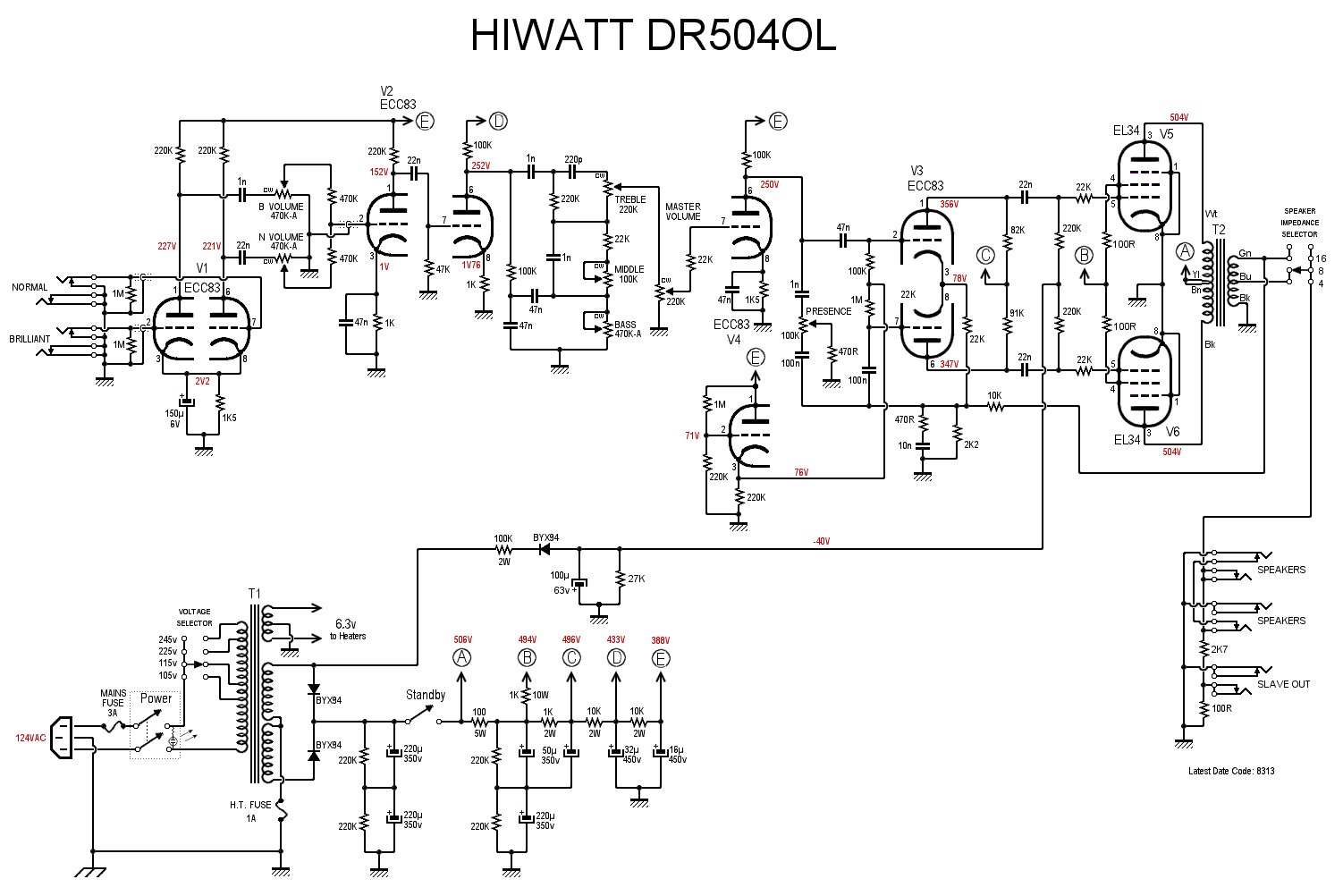
The old Hiwatts also had 22k grid stoppers on each power tube but only 100k bias splitters. This schematic shows 22k grid stoppers with 220k bias splitters which is really pushing it imo. If I use 220k splitters I'll use 5k6 stoppers. My guess is that 100k splitters is a carry over from the early 12AT7 PI models but this will use a 12AX7 PI. So I will likely go the 220k/5k6 route.