
B
Beam Tetrode
Member
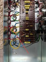
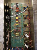
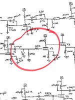
Look at V2 socket, pin 2. Signal is delivered by the shielded grey wire to the 220K grid stopper, then to V2 grid (pin 2). That's perfectly good, but we also have a green wire on pin 2 heading to the 470K grid leak resistor on the main board. This means the 470K grid leak is connected AFTER the 220K stopper. This forms a voltage divider (signal attenuation) which is NOT how the real dookie amps were configured.
In the real dookie mod, the 470K grid leak is always connected BEFORE the 220K stopper. See attached schematic and photos for comparison. Is this an error from Marshall, or intentional design change?
In the real dookie mod, the 470K grid leak is always connected BEFORE the 220K stopper. See attached schematic and photos for comparison. Is this an error from Marshall, or intentional design change?
Attachments
Last edited:


