A
Anonymous
Guest
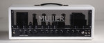
This is great stuff, Olaf! Once again, I'll spend more time tonight! Who makes the enclosure you are using for the footswitch and what model is it?
Steve
Steve

duesentrieb":3ttxsd56 said:Look at the manual switch (which you should install too:")
The manual switch has three PINs. Two for the relays, one for ground.sah5150":1wub3jiy said:duesentrieb":1wub3jiy said:Look at the manual switch (which you should install too
Oh, btw, how would I hook up both a manual switch and a relay? Hmmm.....
Steve
Are you talking about a standard DPDT manual switch? I'm not following you here... I thought you were saying I should have both manual DPDT switches and the relays so that someone could switch sounds without the footswitch by walking up to the amp and flipping a manual DPDT switch... I'm sorry man - I'm a little slow here...duesentrieb":tf3l0vli said:The manual switch has three PINs. Two for the relays, one for ground.sah5150":tf3l0vli said:duesentrieb":tf3l0vli said:Look at the manual switch (which you should install too
Oh, btw, how would I hook up both a manual switch and a relay? Hmmm.....
Steve
You just run additional (parallel) wires from the manual to the 5-PIN (=3), then add the pwr supply (4) and the fifth is for the loop relay (5).
duesentrieb":8lbpndij said:You can have both: manual switch and footswitch, Steve.
Firstly the manual switch is wired, the footswitch (or better the 5 PN jack) is just wired parallel to the manual switch(es) and get additionally a 5-6V supply (for the relays of the footswitch and LEDs inside the footswitch). That goes for all relays - you need three:
one for plexi/800s
one for 800s/Jose
one for the loop.
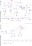
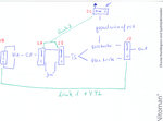
The manual switch layout is shown on my piece of paper - I will add the midi-jack to the final version then.
Solved?

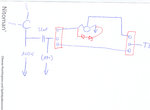
duesentrieb":1p3o4pmf said:Now to the Jose, Steve.
Firstly I think your schem is a bit confusing . . . IMO the Jose is in series with the signal between the CF and the TS - yours is parallel . . . . I'll add a pic