duesentrieb
Well-known member
Hi Steve 
After triple checking everything (and being confused with some LED wiring) I can't find an error somewhere.")
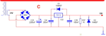
The only thing I would think about is to install an extra transformer for your 6V supply to avaoid popping and overstressing the heater-winding. With 10 relays or so I think its better to use a small 6V AC tranny and use a voltage regulator - just a suggestion though, I know that Peter, back when he modded Marshalls, had no problem to hook 12 ECC83 to a standard Marshall transformer and suck almost 10 Ampêres from it - all of them still running until today of course
After triple checking everything (and being confused with some LED wiring) I can't find an error somewhere.
The only thing I would think about is to install an extra transformer for your 6V supply to avaoid popping and overstressing the heater-winding. With 10 relays or so I think its better to use a small 6V AC tranny and use a voltage regulator - just a suggestion though, I know that Peter, back when he modded Marshalls, had no problem to hook 12 ECC83 to a standard Marshall transformer and suck almost 10 Ampêres from it - all of them still running until today of course