You are using an out of date browser. It may not display this or other websites correctly.
You should upgrade or use an alternative browser.
You should upgrade or use an alternative browser.
duesentrieb
Well-known member
A
Anonymous
Guest
Thanks so much, Olaf! BTW - sent you a PM - would love to see some detailed pics of your stuff to make sure I understand and am doing it right...
Steve
Steve
duesentrieb
Well-known member
last thing before I start to emulate Picasso and draw a bit 
Three channels/or sounds means that you need two relays (double pole).
Both off: sound 1
first on, second off: sound 2
first off, second on: sound 3
In this scenario you need just four PINs of the midi jack:
1: on/off relay 1
2: on/off relay 2
3: supply (5-6Volt)
4 (or 5:") ground
ground
Three channels/or sounds means that you need two relays (double pole).
Both off: sound 1
first on, second off: sound 2
first off, second on: sound 3
In this scenario you need just four PINs of the midi jack:
1: on/off relay 1
2: on/off relay 2
3: supply (5-6Volt)
4 (or 5
duesentrieb
Well-known member
My pleasure.sah5150":26d3iz39 said:Thanks so much, Olaf! BTW - sent you a PM - would love to see some detailed pics of your stuff to make sure I understand and am doing it right...
Steve
Kids played with the cam, battery is empty - so a bit later (or tomorrow), sorry, but thats so typical - if the old fart needs something the kids have abused it before
You'll have three sounds, right?
A
Anonymous
Guest
duesentrieb":vyzu540h said:My pleasure.sah5150":vyzu540h said:Thanks so much, Olaf! BTW - sent you a PM - would love to see some detailed pics of your stuff to make sure I understand and am doing it right...
Steve
Kids played with the cam, battery is empty - so a bit later (or tomorrow), sorry, but thats so typical - if the old fart needs something the kids have abused it before
You'll have three sounds, right?
I'll be switching a gain stage in and out (including gain and master pots) - I need (I think) 3 relays for that. I also would like to switch two different masters (one with diode clipping and different positioning) in one of the modes. So yes 3 sounds:
Sound 1 : Super Lead (with a gain and master though)
Sound 2a : Added gain stage with "regular" 800 master
Sound 2b : Added gain stage with "jose" (diode clipping master)
I want these all footswitchable and I would also like to be able to footswitch on/off the effects loop
I wanted two LEDs corresponding to the two main sounds (regardless of master on Sound 2) - Super Lead mode and Rodded Super Lead mode,
So footswitching switching between the 3 sounds and switch on/off the effects loop.
I think I need two relays for switching in and out the gain stage (Sound 1 to Sound 2), 1 relay to switch between the two master pots when going Sound 1 to Sound 2, 1 relay for switching between the Jose master and regular 800 master in Sound 2 (2a -2b) and another to relay to switch on and off the effects loop. 5 relays total I think... Maybe I should send you pdfs of my preamp design....
I know... complicated
Steve
duesentrieb
Well-known member
No, not complicated - just hard to explain with broken english 
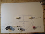
Here's the layout for the power supply off the heaters, the relays (add a diode over its coil - check coil orientation with a 9V block battery) and the LEDs - with a manual on/off/on switch.
Middle position: nothing happens to the relays (sound 1 - pic to follow)
up: relay 1 is on (minus is switched to ground)
down: relay 2 is on (1 off, minus to ground)
As you can see the LED is in parallel to the relay coil (so its on, when the relay is on - which means no LED for sound 1 or a permanent LED (wired differently of course). Do the same with (diode+LED+resistor) with the left relay. The longer lead/wire of the LED is its "+".
Attachments
duesentrieb
Well-known member
Some questions:sah5150":34lkrrbq said::
Sound 1 : Super Lead (with a gain and master though)
Sound 2a : Added gain stage with "regular" 800 master
Sound 2b : Added gain stage with "jose" (diode clipping master)
- sound 1 is like a 2 gainstages 800s (location of gainpot is after 1st gainstage I assume?)
- sound 2 uses the same master as 1 - I don't hope so - adding its own master is easier
- sound three has four gainstages (or three?) and do you have a prewired-"extra" master - or should the diodes be switched in to the master of sound 2?
A
Anonymous
Guest
Thanks, Olaf - I'll spend a bunch more time digging into your explanantions tonight. My goal is to update my preamp design schematics with the switching...
Steve
Steve
duesentrieb
Well-known member
Gotcha - should have read more carefully.sah5150":2mj85h6s said:I think I need two relays for switching in and out the gain stage (Sound 1 to Sound 2), 1 relay to switch between the two master pots when going Sound 1 to Sound 2, 1 relay for switching between the Jose master and regular 800 master in Sound 2 (2a -2b) and another to relay to switch on and off the effects loop. 5 relays total I think... Maybe I should send you pdfs of my preamp design....
I know... complicated
Steve
The fx loop switching needs an extra relay - so yes, three. All of them double pole (like shown) or 6, 3 pairs. And then you'll need all PINs of that midi thing.
I'll draw you something . . .
The problem (?) might be the diodes (Jose), not sure if that pops like a mega tube fart or not - I'll try that here.
Gimme 2-3 days and it'll be drawn.
CU
A
Anonymous
Guest
duesentrieb":2n0wfff7 said:Gotcha - should have read more carefully.sah5150":2n0wfff7 said:I think I need two relays for switching in and out the gain stage (Sound 1 to Sound 2), 1 relay to switch between the two master pots when going Sound 1 to Sound 2, 1 relay for switching between the Jose master and regular 800 master in Sound 2 (2a -2b) and another to relay to switch on and off the effects loop. 5 relays total I think... Maybe I should send you pdfs of my preamp design....
I know... complicated
Steve
The fx loop switching needs an extra relay - so yes, three. All of them double pole (like shown) or 6, 3 pairs. And then you'll need all PINs of that midi thing.
I'll draw you something . . .
The problem (?) might be the diodes (Jose), not sure if that pops like a mega tube fart or not - I'll try that here.
Gimme 2-3 days and it'll be drawn.
CU
Cool - can you give me your email address and I'll send you the preamp scenamtics so you can see what I have going?
Steve
duesentrieb
Well-known member
Sure
drolafkrampe (at) t-online (dot) de
drolafkrampe (at) t-online (dot) de
A
Anonymous
Guest
Here is the preamp up to the efx loop

A
Anonymous
Guest
Here is the efx loop and other masters:

duesentrieb
Well-known member
V2A needs a grid stopper (can be small like V1B/68k), Steve.
The loop bypass switch needs two 2M2 droppers (also when rela is used instead of a manual switch).
The loop bypass switch needs two 2M2 droppers (also when rela is used instead of a manual switch).
A
Anonymous
Guest
duesentrieb":2gdqqgq8 said:V2A needs a grid stopper (can be small like V1B/68k), Steve.
The loop bypass switch needs two 2M2 droppers (also when rela is used instead of a manual switch).
Understand comment one. What are "droppers" and where do they go?
Steve
A
Anonymous
Guest
Also, just to be clear. All those DPDT manual switches need to be replace by relays. The only manual switch I want to have is on the back of the amp - the SPDT switch shown in the second schem to switch between series/parallel efx loop - I don't think anyone would be doing that in real time while playing. So all the manual switches need to somehow be footswitchable except that one. That is why I think I need so may relays...
Steve
Steve
duesentrieb
Well-known member
They put both "lines" (fx in or out) with 2M2 to ground - when switched the circuit "sees" 2M2 and is not hanging in the air - and pops because of the level differences.sah5150":26jlr50o said:duesentrieb":26jlr50o said:V2A needs a grid stopper (can be small like V1B/68k), Steve.
The loop bypass switch needs two 2M2 droppers (also when rela is used instead of a manual switch).
Understand comment one. What are "droppers" and where do they go?
Steve
duesentrieb
Well-known member
Look at the manual switch (which you should install toosah5150":1ahulyx6 said:Also, just to be clear. All those DPDT manual switches need to be replace by relays. The only manual switch I want to have is on the back of the amp - the SPDT switch shown in the second schem to switch between series/parallel efx loop - I don't think anyone would be doing that in real time while playing. So all the manual switches need to somehow be footswitchable except that one. That is why I think I need so may relays...
Steve
The footswitch has four switches: three for each sound (latching) and one for the loop (a normal).
The three sound switches are hooked to two more relays (inside the footswitch, powered by the pwr supply !) like a flip flop - you can freely switch between the three. The loop is like an oldschool channel switch (for the loop though), which either puts it (it = the internal relay) to ground or not:
Here's the footswitch (three switches for the three sounds)

Just imagine the fourth for the loop additionally.
Schem for the footswitch:

The power is here supplied with a jack - thats not necessary for you (5 PINs, one of them for power). You need 6 additional diodes (1N4007) and 2 Takamisawa relays. Those are not like the relays you have now, but "flip flop" relays. If you hit one switch it does two things at the same time: selects the corresponding relay into its correct position and put the other to "bypass" - sounds complicated but is actually pretty simple.
I can send you one (with the additional loop switch) if you have difficulties with it - I've built 20-25 so far, mostly for Einstein users to switch between channel 1 modes - but I'm using it also for my own amps (3 channels or 2 channels with additonal mode for one of the channels). Works like a charm . . .
duesentrieb
Well-known member
http://www2.produktinfo.conrad.com/date ... _2A_5V.pdf
Thats the footswitch relay (sorry, german)
Takamisawa RAL5WK is the correct type. As you can see it has two coils (one to switch it on, one to switch it off).
Thats the footswitch relay (sorry, german)
Takamisawa RAL5WK is the correct type. As you can see it has two coils (one to switch it on, one to switch it off).