@ Steve

  • Thread starter Thread starter duesentrieb
  • Start date Start date
duesentrieb":24v8krpa said:
sah5150":24v8krpa said:
duesentrieb":24v8krpa said:
btw - don't be too confused that this layout for the PPIMV is a bit different to Larry/Rockstahs. They just add 2M2 for safety and instead of a 250 there's a 500k - and then (with a 250k) no 220ks are needed. Still no ground, you see ;)
Without the 220Ks where does the return wire from the pot go?

Steve
Do you see the error in the schem now?
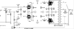
Yes, I'm just not exactly sure how to fix it. :D

Steve
 
richmod6.jpg
 
I've edited one post Steve. Black, not blue . ..

3 are tied together in yours and then are hooked to the bias supply.
1 are coming from the PI ube
2 are going to the 5k6 stoppers.
 
duesentrieb":1grk0650 said:
I've edited one post Steve. Black, not blue . ..

3 are tied together in yours and then are hooked to the bias supply.
1 are coming from the PI ube
2 are going to the 5k6 stoppers.

Actually, you were right the first time. It is a blue wire in Mark's layout diagram coming from the pot out back to the bias supply. Black wires are all going from .1 uF -> pin 5...

Cool - this I finally figured out - schem almost done. What I don't understand is the presence/density stuff. In my 50W Egnater amp it goes

8 OHM secondary -> 47k -> Density (.0047uF from wiper to pot out) -> Presence (.1uF from wiper to pot out) -> Ground

This works cool in the Egnater 50 Watter...

Are you saying:

8 OHM secondary -> Density (.0047 from wiper to pot out) -> .1 uF -> Presence (25K from wiper to pot out) -> 4.7K -> Ground

??

Steve
 
Ok, I think this version fixes everything. The only issue is the presence wiring suggestion you made which I have questions about above. I believe the Density will work as is since it works in my Egnater 50 Watter, unless the 47K needs to go up for a 100 Watter?? Anyway, I look forward to you answering my questions above, Olaf. I verified the Density/Presence wiring in my Egnater 50 Watter, I just want to understand your suggestions as well. Anyway, the updated schem:

100Watt2ChannelPowerAmp_6.JPG


Thanks!

Steve
 
Here Steve:
R35 = 47k
hooked to 16 Ohm
C23 is also to get rid of the DC on the pot (like C19)
 

Attachments

  • Bild 4.png
    Bild 4.png
    83.6 KB · Views: 1,185
Bias:

R67 = 22k
D5 = 4007
C25, C26 = 10µF (or 8)
R53 = 47k

The pot (VR11) is not hooked to ground, its a variable resistor, not a divider
 

Attachments

  • Bild 5.png
    Bild 5.png
    15 KB · Views: 1,164
PPIMV looks good now. Bias is not correct.
47k is located before the density (or better: between presence and density), not after.
 
Filtering:

Bridge --> 2x100 (2 caps) --> fuse --> choke --> 2x100 (2 caps) --> resistor --> PI supply (1 cap) --> 4k7 --> loop supply (10-22µF) ---> resistor ---> preamp supply (1 cap)

1 cap = 50µF/50µF
 
Olaf - your RULE! I'll work on the updates now - had to take my Mom to the movies (she's visiting)... :)

Steve
 
duesentrieb":va460k5z said:
Filtering:

Bridge --> 2x100 (2 caps) --> fuse --> choke --> 2x100 (2 caps) --> resistor --> PI supply (1 cap) --> 4k7 --> loop supply (10-22µF) ---> resistor ---> preamp supply (1 cap)

1 cap = 50µF/50µF

Ok, Olaf, here is a new version. This time I believe I have the Presence and Density taken care of. I grounded the Density pot because I couldn't figure out what else to do with it since your image is cut off. Is this correct? I also have the bias supply correct, I believe. It is not exactly like your image, but I believe it is identical to the Super Bass schem you put in an earlier post. I also believe that the filtering is idential to the Super Bass layout you provided, which (I believe) is what I want. This does not match what you have listed above. I know my schem looks different visually, however I believe if you follow it carefully, the filtering is identical to the Super Bass schem you sent. Can you confirm. Unless there is a good reason to do something different, I think this is correct to the Super Bass... I have 6 50uF/50uF caps as expected for Super Lead/Bass (5 on this schem, 1 on the preamp schem). Anyway, here it is:

100Watt2ChannelPowerAmp_7.JPG


Thanks!

Steve
 
Hi Steve,

looks good.
Filtering is good. Sorry for the confusion, I was confused :D
The third pin of the deep isn't used (doesn't go to ground).
 
duesentrieb":2ez9m79o said:
Hi Steve,

looks good.
Filtering is good. Sorry for the confusion, I was confused :D
The third pin of the deep isn't used (doesn't go to ground).

Awesome! Thanks Olaf! Now for the footswitch.. :D

Steve
 
Ok Olaf - here is my first shot at the footswitching. Mine is alot different than yours because I have two sound modes, a different master for each and a loop on/off switch. Maybe I don't quite understand how latching relays work, but I think I'm close here. If you refer to the other schematics, the first relay in the footswitch switches between Plex mode and Rod mode (PLEX_MODE, ROD_MODE and MASTER_MODE off = Plex mode, PLEX_MODE, ROD_MODE and MASTER_MODE On = Rode mode). Relay 2 in the footswitch switches the ZEN_MASTER relay on and off. This puts the Jose master into the circuit and switches out the regular masters regardless of whether we are in plex or rod mode. Relay 3 in the footswitch switches the LOOP_ON/OFF relays on and off. This takes the loop in and out of the circuit. The Loop and Zen_Master footswitches had to be SPDT so that I can turn them on and off from a single switch. The Rod mode and plex mode footswitches are just SPST momentary switches. Note that in either rod or plex mode, if the Zen master is switched on, the plex or rod mode LED is on on the footswitch as well as the Zen mode LED. This is by design....

100Watt2ChannelFootSwitching_2.jpg


Thanks man!

Steve
 
Back
Top