ledvedder
Well-known member
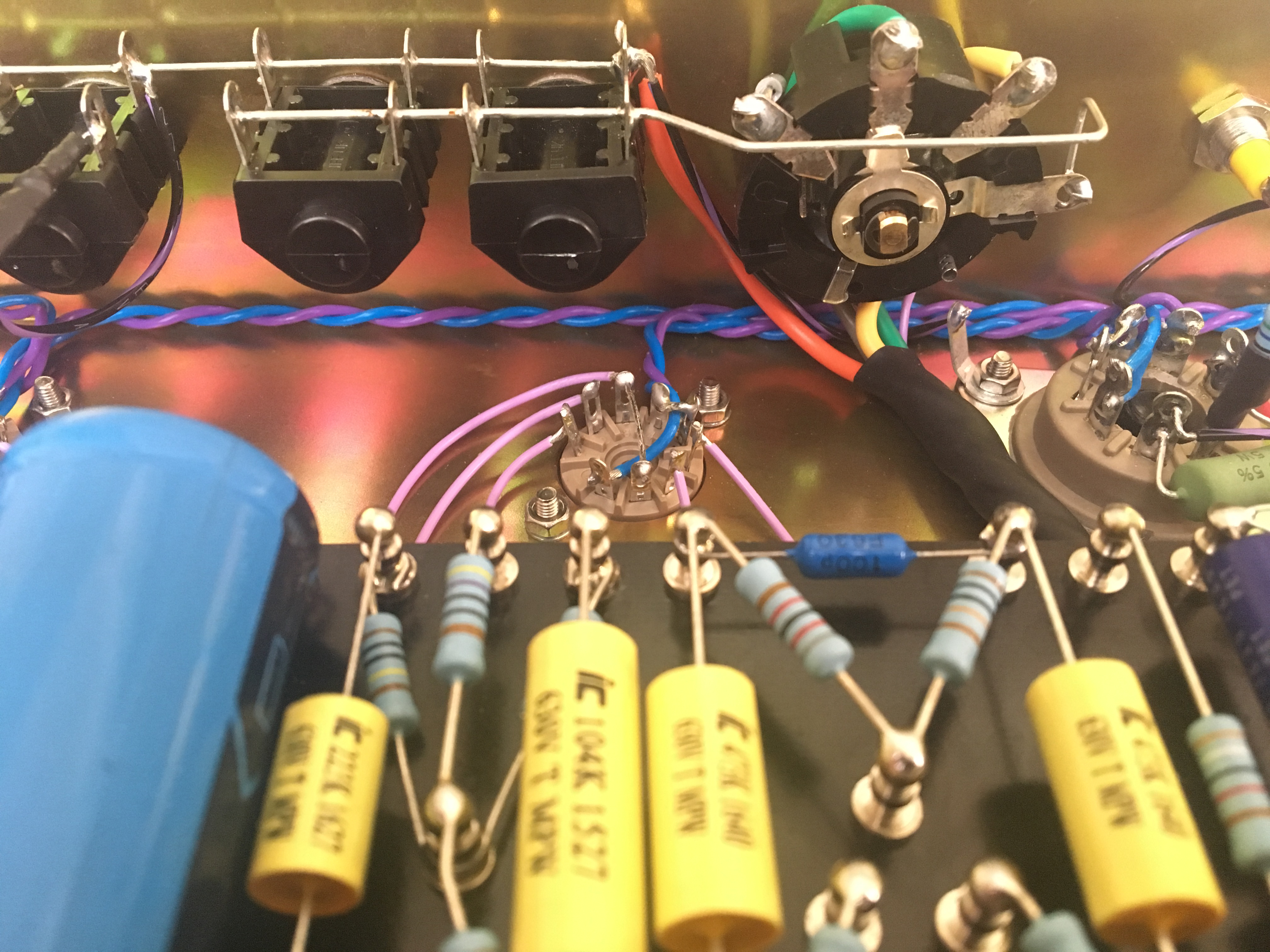
I really mucked up this ground point turret at the preamp filter cap. Any recommendations on cleaning this up?

Ok, here's some voltages that I got.
V1 pins 1-9 -
238v
1.2mv
2.6v
-1.8mv
-1.8mv
203v
-0.4mv
1.7
0.4mv
V2 pins 1-9 -
155v
4.7mv
1v
-1.8mv
0.5mv
276v
157v
-1.8mv
V3 pins 1-9 -
216v
1.5mv
34.6v
-1.6mv
-0.5mv
201v
0.7mv
34.6v
-1.6mv
Power filter caps -
442v
442v
312v
440v
Preamp filter cap -
267v
275v
V1 node -
266v
B+ onto turret board -
441 v
B+ after 1st dropping resister (22k) and at PI node -
312v
Just that buzz that's in the video. And the scratching on the preamp pot.You're just getting hum/buzz? Or you're also getting HF oscillation?
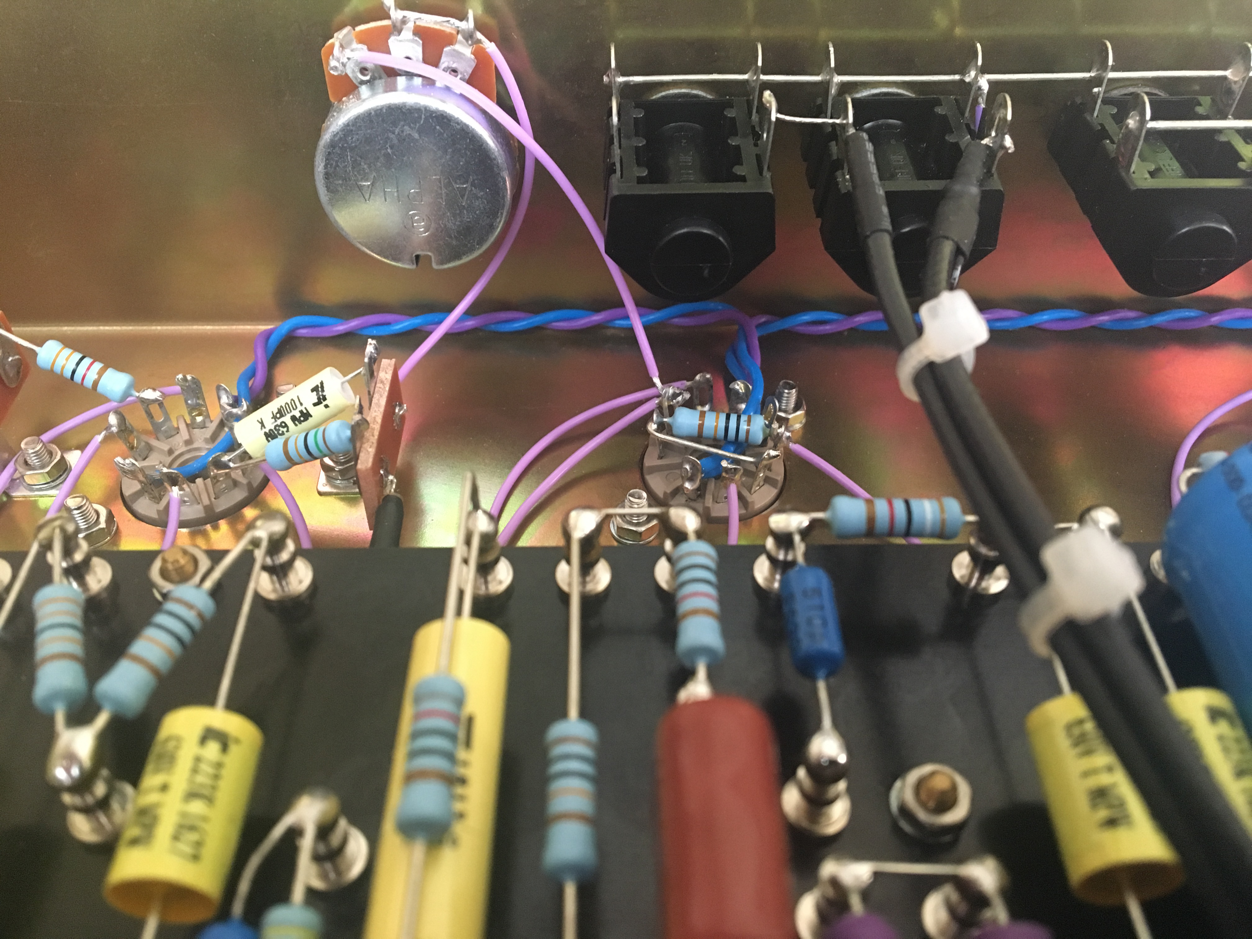
That was coming from the 2 68k resistors when I was initially going to make it a switchable 2204/1987. I left it in in case I decide to add that mod in the future. It's disconnected and heatshrinked at both ends.What’s the green wire in the bottom pic going nowhere?
Even though it’s disconnected it can still couple electromagnetic energy and transmit it to another part of the circuit since it’s basically a series inductor that’s sensing whatever magnetic field is nearby. If your intentions are to leave it then you must ground one part of the wire. If that causes problems for functionality then you need to completely remove it. When we suggested bone stock 2204, we really mean bone stock - no additional wiring at this stage. Anything that has no purpose has to be removed here because wiring and layout can cause instability quite easily without hassle. Yes it’s more work, there’s no shortcuts with these amps.That was coming from the 2 68k resistors when I was initially going to make it a switchable 2204/1987. I left it in in case I decide to add that mod in the future. It's disconnected and heatshrinked at both ends.
OK, I'll remove that wire and the 2 unused 68k resistors. I'll also confirm none of those wires are crossing.Even though it’s disconnected it can still couple electromagnetic energy and transmit it to another part of the circuit since it’s basically a series inductor that’s sensing whatever magnetic field is nearby. If your intentions are to leave it then you must ground one part of the wire. If that causes problems for functionality then you need to completely remove it. When we suggested bone stock 2204, we really mean bone stock - no additional wiring at this stage. Anything that has no purpose has to be removed here because wiring and layout can cause instability quite easily without hassle. Yes it’s more work, there’s no shortcuts with these amps.
As far as wiring for the first stage, make sure the grid, plate, and cathode of one side of the tube doesn’t cross with the grid, plate, and cathode of the other side of the tube. They’re different phases (and all at various voltage potentials) of amplification and if they are near, you can get buzzing and instability. It matters most in the first few stages because anything that happens there is only amplified down the circuit further and further.
I just came back to the last two pages of this thread. (but just appease everyone and put a baking tray over the chassis). Hang in there.
I won't reiterate other suggestions. Here are a couple different thoughts, based on your last buzz video and photos.
- I'd replace that large metal oxide resistor with a half-watt carbon film resistor (10k). Smaller might be better here.
- The buzz dropped when you put the alligator clip on the cathode side of the 10k resistor. That makes me think there is an issue with the tube itself.
- what happens if you clip the ground side of the 10k to the ground side of the 2k7 resistor (or some other ground point)?