screamindemon
Well-known member
If I have a mustard cap that reads 22000 could you please tell me the value ?
Thanks so much for all your help !
Thanks so much for all your help !
screamindemon":3ojtu6yz said:So, I fired it up last night and I may have a problem.
I put a new set of matched EL 34s in it and hooked up my Bias right and was getting about 450 volts per plate then switched to cathode current and reading went to zero.
My have a problem with the Bias rite, put in new battery no change.
going to test it out on one of my other amps today and try and figure out whats going on.
Hopefully I didn't mess anything up, but I think everything is right.
sjk":38o1ejr0 said:screamindemon":38o1ejr0 said:So, I fired it up last night and I may have a problem.
I put a new set of matched EL 34s in it and hooked up my Bias right and was getting about 450 volts per plate then switched to cathode current and reading went to zero.
My have a problem with the Bias rite, put in new battery no change.
going to test it out on one of my other amps today and try and figure out whats going on.
Hopefully I didn't mess anything up, but I think everything is right.
I had a weber bias right that worked great for about 3,4 years and then stopped giving good readings and started doing funky stuff. If you have a multimeter you could read bias by putting black probe to chassis and then the red probe to the 1 watt resistor soldered between ground and cathode pin on each tube socket. That is how I do it now and it seems a little more accurate then bias meters and such. It is more dangerous so you have to be more careful obviously.
screamindemon":1bghscmv said:sjk":1bghscmv said:screamindemon":1bghscmv said:So, I fired it up last night and I may have a problem.
I put a new set of matched EL 34s in it and hooked up my Bias right and was getting about 450 volts per plate then switched to cathode current and reading went to zero.
My have a problem with the Bias rite, put in new battery no change.
going to test it out on one of my other amps today and try and figure out whats going on.
Hopefully I didn't mess anything up, but I think everything is right.
I had a weber bias right that worked great for about 3,4 years and then stopped giving good readings and started doing funky stuff. If you have a multimeter you could read bias by putting black probe to chassis and then the red probe to the 1 watt resistor soldered between ground and cathode pin on each tube socket. That is how I do it now and it seems a little more accurate then bias meters and such. It is more dangerous so you have to be more careful obviously.
Thanks for the info but I'm not sure which pin that is ?
sjk":1968ysvn said:screamindemon":1968ysvn said:sjk":1968ysvn said:screamindemon":1968ysvn said:So, I fired it up last night and I may have a problem.
I put a new set of matched EL 34s in it and hooked up my Bias right and was getting about 450 volts per plate then switched to cathode current and reading went to zero.
My have a problem with the Bias rite, put in new battery no change.
going to test it out on one of my other amps today and try and figure out whats going on.
Hopefully I didn't mess anything up, but I think everything is right.
I had a weber bias right that worked great for about 3,4 years and then stopped giving good readings and started doing funky stuff. If you have a multimeter you could read bias by putting black probe to chassis and then the red probe to the 1 watt resistor soldered between ground and cathode pin on each tube socket. That is how I do it now and it seems a little more accurate then bias meters and such. It is more dangerous so you have to be more careful obviously.
Thanks for the info but I'm not sure which pin that is ?
This page here shows it and can explain it better than me, I'm no amp tech just do a little soldering and amp biasing
https://robrobinette.com/Tube_Bias_Calculator.htm

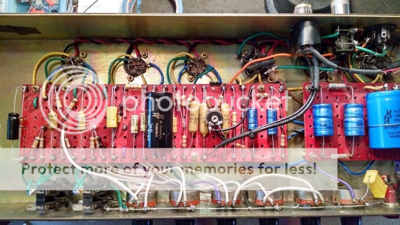
MichaelR/T":ccyd5hpk said:I see some possible problems.
I marked in what the values should be.

screamindemon":1emjjrob said:MichaelR/T":1emjjrob said:I see some possible problems.
I marked in what the values should be.
I think those value are correct, I will double check.
That is if I am reading these cap values correct !
screamindemon":24tlegg3 said:MichaelR/T":24tlegg3 said:I see some possible problems.
I marked in what the values should be.
I think those value are correct, I will double check.
That is if I am reading these cap values correct !
screamindemon":1uh2defn said:I am going to order a new bias meter next week.
I was reading where you can take a 1ohm 1 watt resister from pin 8 to ground and take your cathode current reading there.
I see a resister soldered between pin 1 and 8 on my power tubes sockets, could this be the same as the resister to ground ? Or is this for something else?
Thanks
sjk":39j2gd29 said:screamindemon":39j2gd29 said:I am going to order a new bias meter next week.
I was reading where you can take a 1ohm 1 watt resister from pin 8 to ground and take your cathode current reading there.
I see a resister soldered between pin 1 and 8 on my power tubes sockets, could this be the same as the resister to ground ? Or is this for something else?
Thanks
Thats it the one to make the reading on your powertube socket. I don't know a whole lot about amps but I do recognize that fwiw.